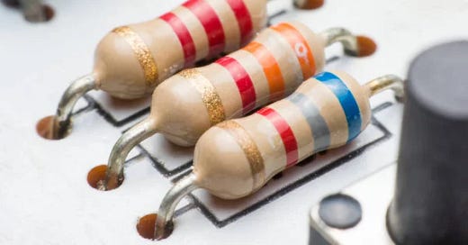
Resistors are out to get ya
Resistors in op-amp circuits tend to behave in unexpected ways. PCB ground planes come with similar gotchas, too.
If you dabble in electronics, you know that some components exhibit markedly undesirable electrical characteristics that can get in the way of your designs. For example, electrolytic capacitors have a fair amount of internal resistance that makes them less-than-ideal for decoupling power supply lines of digital chips.
On the flip side, for small components — such as ceramic capacitors, chip inductors, signal transistors, or diodes — we get used to the idea that they behave more or less as advertised until we start mucking with very high signal frequencies, perhaps 100 MHz or more.
But what about resistors? Well, that’s a funny story! We do expect them to have some series inductance — they are made out of a length of a conductor after all — but except for wirewound resistors, the effect is fairly negligible below gigahertz signal speeds.
Less intuitively, a resistor also bears some semblance to a capacitor: it’s made out of a piece of poorly-conductive material sandwiched between two metal terminals. Of course, it’s not a very good capacitor — just a fraction of a picofarad — but given how resistors tend to be used, this parallel capacitance is more of an issue than it might seem.
Consider that when presented with a 1 MHz sine wave, a 0.2 pF capacitor has an impedance of ~800 kΩ — the formula, as discussed here, is XC = 1/(2π × f × C). If that 800 kΩ appears in parallel with a 100 Ω resistor, it's not a big deal — and indeed, 100 Ω resistors stay good past 500 MHz. But what if we’re talking about a 1 MΩ resistor used in an op-amp feedback loop? Well, even at this low frequency, the apparent resistance would drop to ~440 kΩ. Oops!
To illustrate the problem in practice, I connected a 1 kΩ resistor in series with a 1 MΩ through-hole resistor to be tested, and then hooked up this contraption to a function generator set to output a sine wave with a peak-to-peak amplitude of 10 V. The resistors formed a voltage divider, and if they maintained their advertised parameters, I would be seeing about 10 mV (0.1% of the input voltage) across the terminals of the smaller one.
But that’s not what happened. At 1 MHz, the voltage across the 1 kΩ resistor measured 20 mV p-p. It would seem that the 1 MΩ resistor was already behaving more like 500 kΩ:
As I cranked up the frequency to 5 MHz, the voltage jumped to ~70 mV p-p, suggesting that we were down to 140 kΩ:
At 20 MHz, we’re looking at 225 mV peak-to-peak, putting the apparent resistance of the large resistor at around 44 kΩ — a massive 96% drop:
Does this matter? As noted earlier, one common application of resistors above 100 kΩ is in the feedback loop for operational amplifiers, especially for faint input signals (e.g., from photodiodes). Another use of large resistances is to bias AC-coupled signals. In both uses, resistor parasitics can significantly attenuate or distort the output at surprisingly low frequencies; no square wave above 200 kHz is safe.
The simplest solution to this problem is to build a two-stage amplifier. The first stage can realize some modest voltage amplification while simultaneously lowering signal impedance. The second stage could, in turn, make up the difference with smaller input and feedback resistors.
As a footnote: this is also why the modern-day PCB design habit of putting ground planes or copper pours everywhere should not be always taken as gospel. The planes can reduce inductance and lower radio frequency interference in high-speed digital circuits, but they also indiscriminately add capacitance across the PCB. The value is nothing to sneeze at — about 0.5 to 1 pF per cm of a signal trace that goes directly over such a plane. For faint, low-current signals, this can be a bad deal.
For more articles about electronics, click here.


