
A nicer voltmeter clock
Sometimes, electronic circuit design is mostly about wood
Back in 2019, I built a simple voltmeter clock:
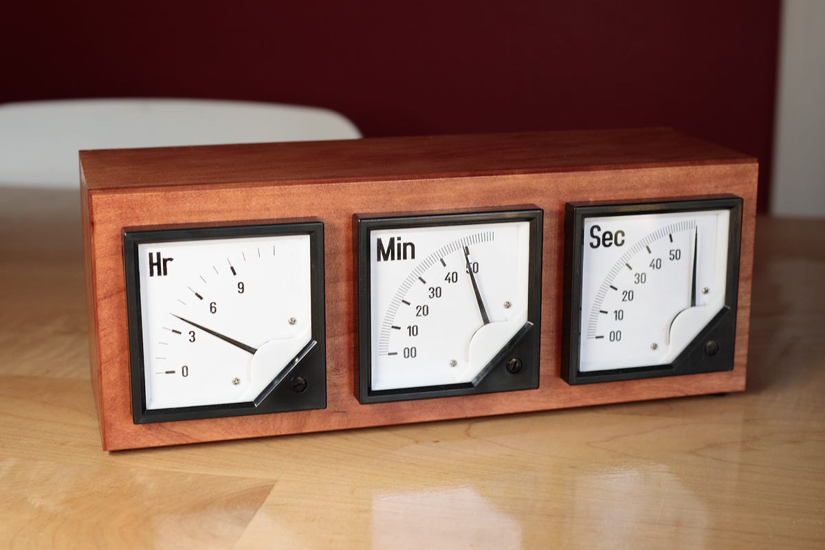
As the name implies, these clocks use analog panel voltmeters instead of traditional clock faces to display time. I didn’t come up with the idea, so I never really blogged about the design; I just built one and kept it on my office desk.
Other people keep building these too, but most of the designs I see on the internet are just… sort of janky. So, I figured it might be good to build a better-looking one and document the process more properly.
The design started with a rough mockup in a 3D design program:
For this version of the meter clock, I used three generic, 90° panel voltmeters from Amazon (link, about $9 a piece). I disassembled them, took careful measurements of the faces, and then printed replacement decals on adhesive paper. Printable PDF templates can be found here.
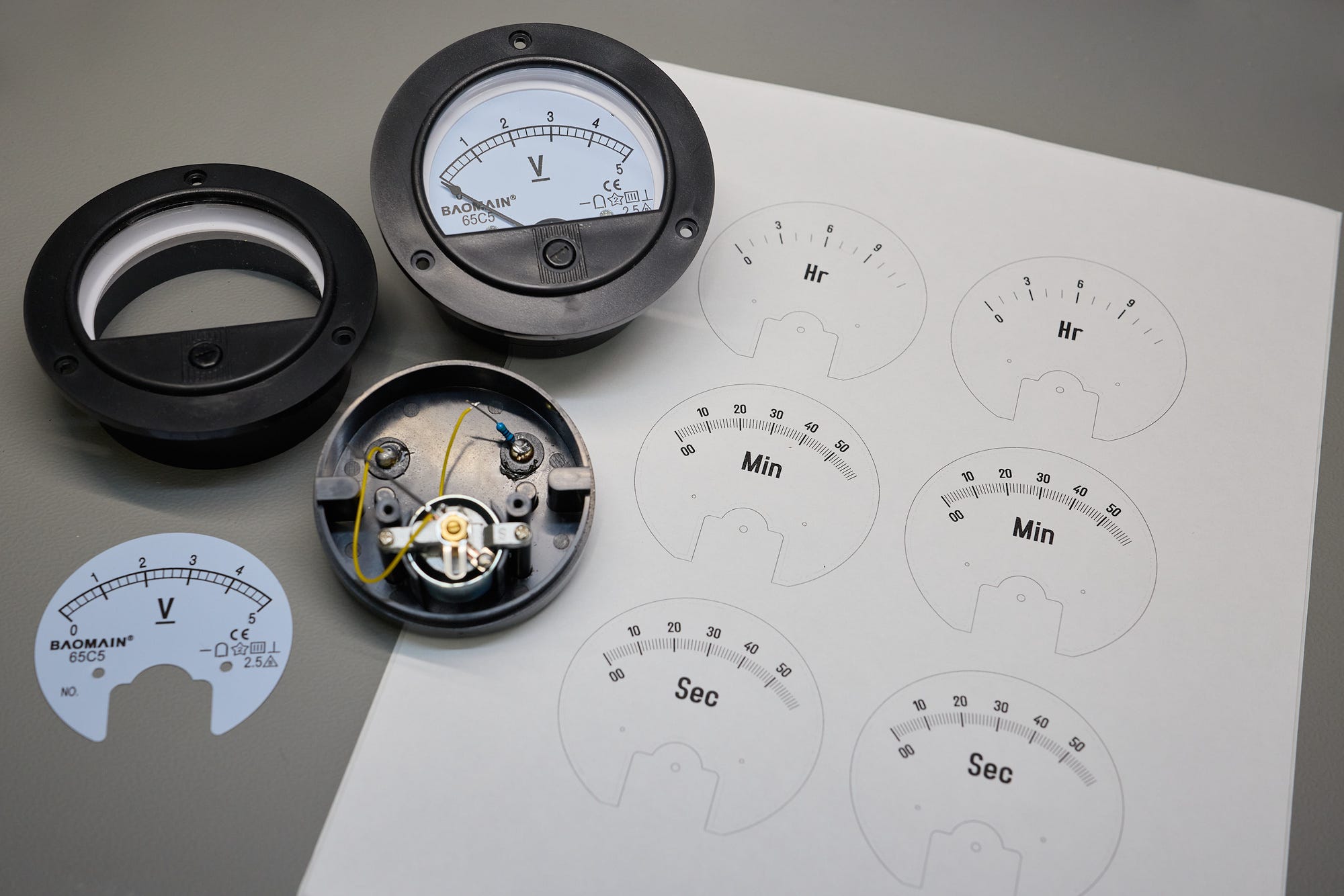
Note that the new hour gauge has 13 divisions, from 0 to 12, while the minute and second templates have 61 divisions, from 00 to 60. This is because I wanted to implement continuous motion for each hand; this meant that at 11:30, the hour dial couldn’t be just stuck at 11; it needed to be moving toward the twelfth division, even if it was never to reach it.
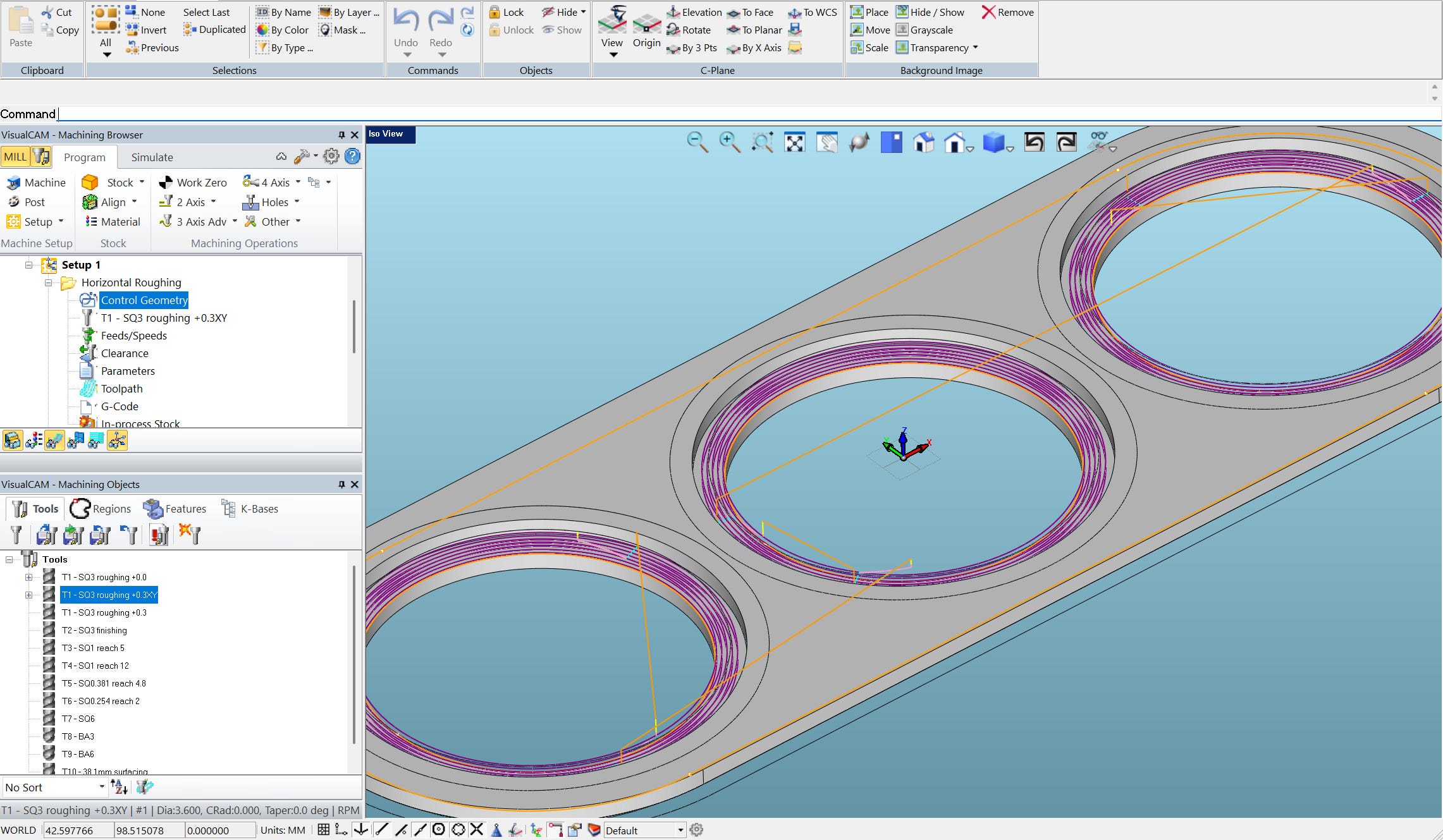
In addition to a host of other problems, the cheap “Baomain 65C5” meters I’m using have a rather hideous plastic flange. I decided to hide this flange from view and use a decorative recessed pattern to keep the front panel interesting. This detail made it more expedient to cut the front and back on a CNC mill instead of making the entirety of the enclosure by hand (as I did for version 1).
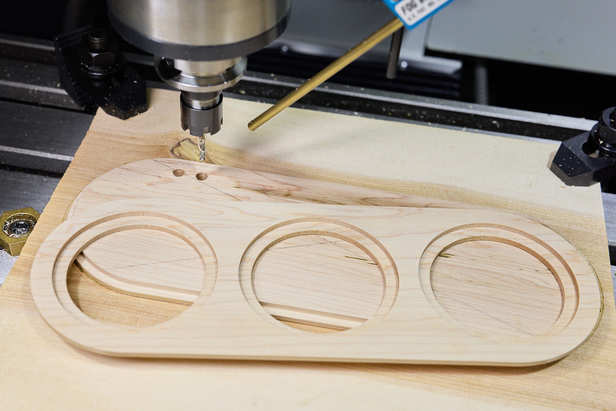
The stock material for the enclosure is maple lumber — resawn, squared, and planed using conventional tools before letting the CNC machine take care of the finishing touches:
Without a CNC mill, the path of least resistance would be to construct the panel as two-part glue-up, each part cut by following a printed (paper) template. A simple way to get the curves perfectly right would be to use a spindle sander.
The curved side wall posed a different challenge. For a seamless appearance, I needed to bend a flat piece of wood to conform to a template. To accommodate the tight radius without a steam bending rig, I opted to cut a series of notches on the inside:
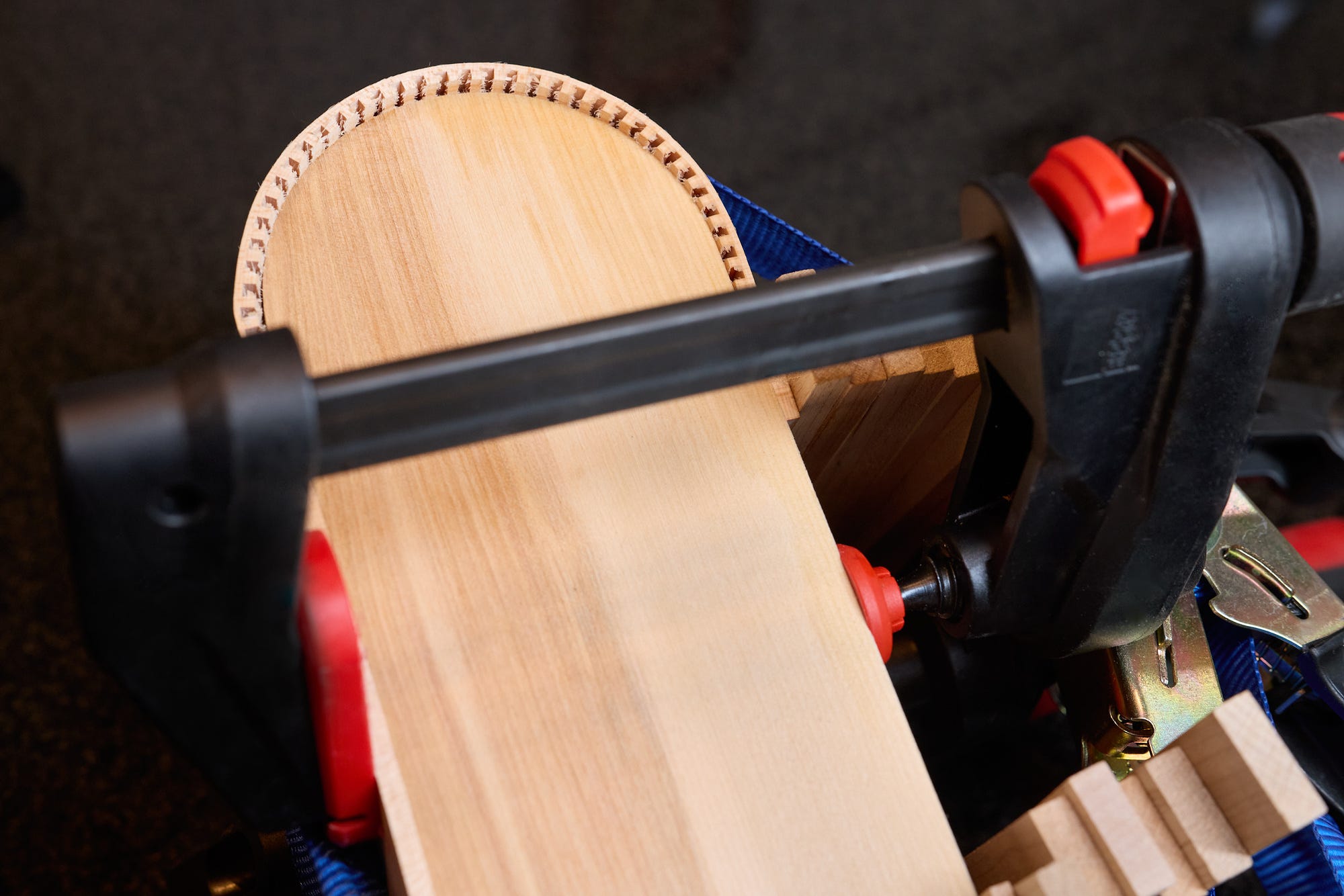
The wood needed to be moistened, clamped, and then allowed to dry. After a couple of days, I glued the curved side wall to the front and back faces. Another template cut out of scrap plywood helped with precise fit without the need for gymnastics with clamps and ratchet straps:
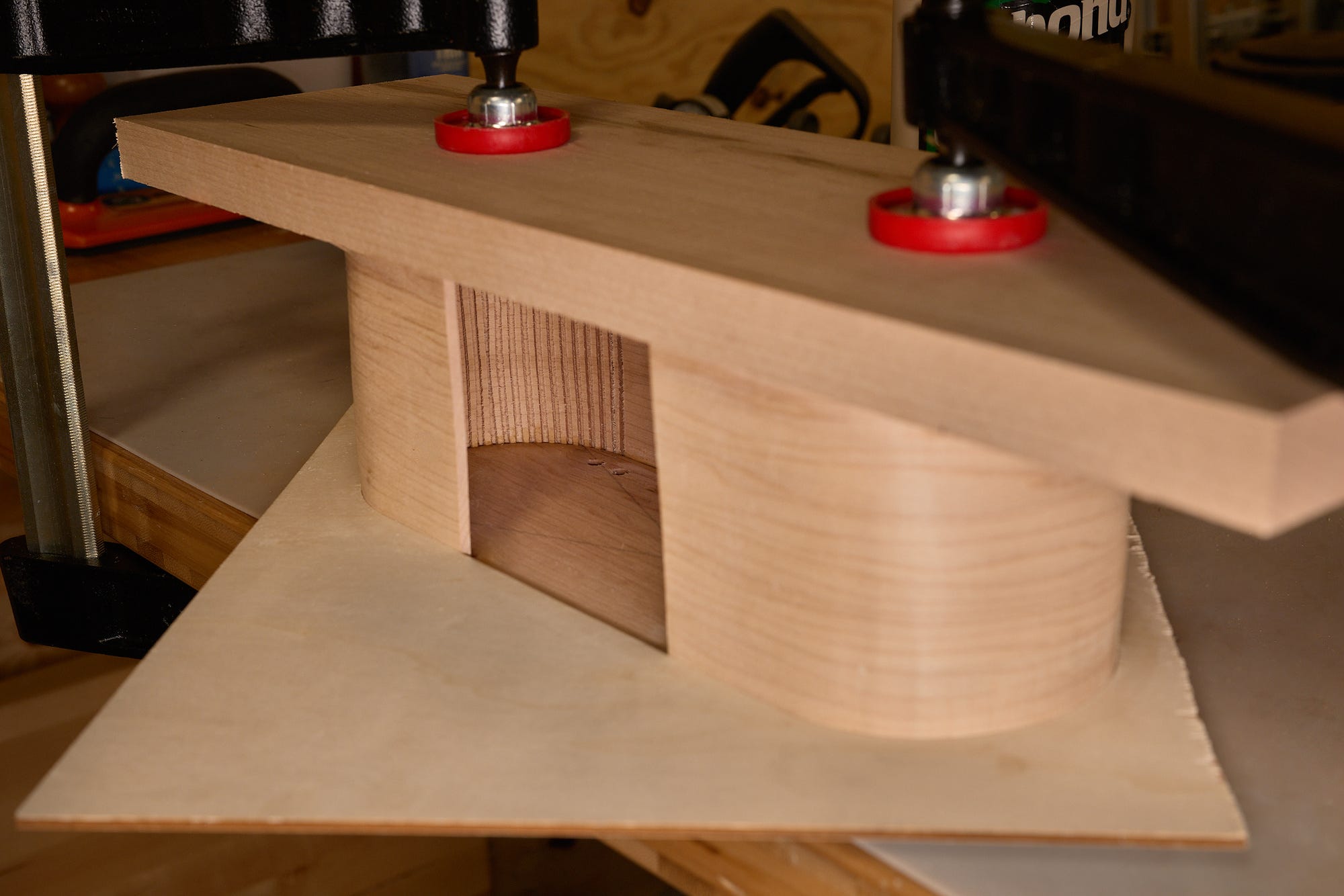
Anyway — here’s the assembled piece after sanding and a coat of nitrocellulose lacquer:
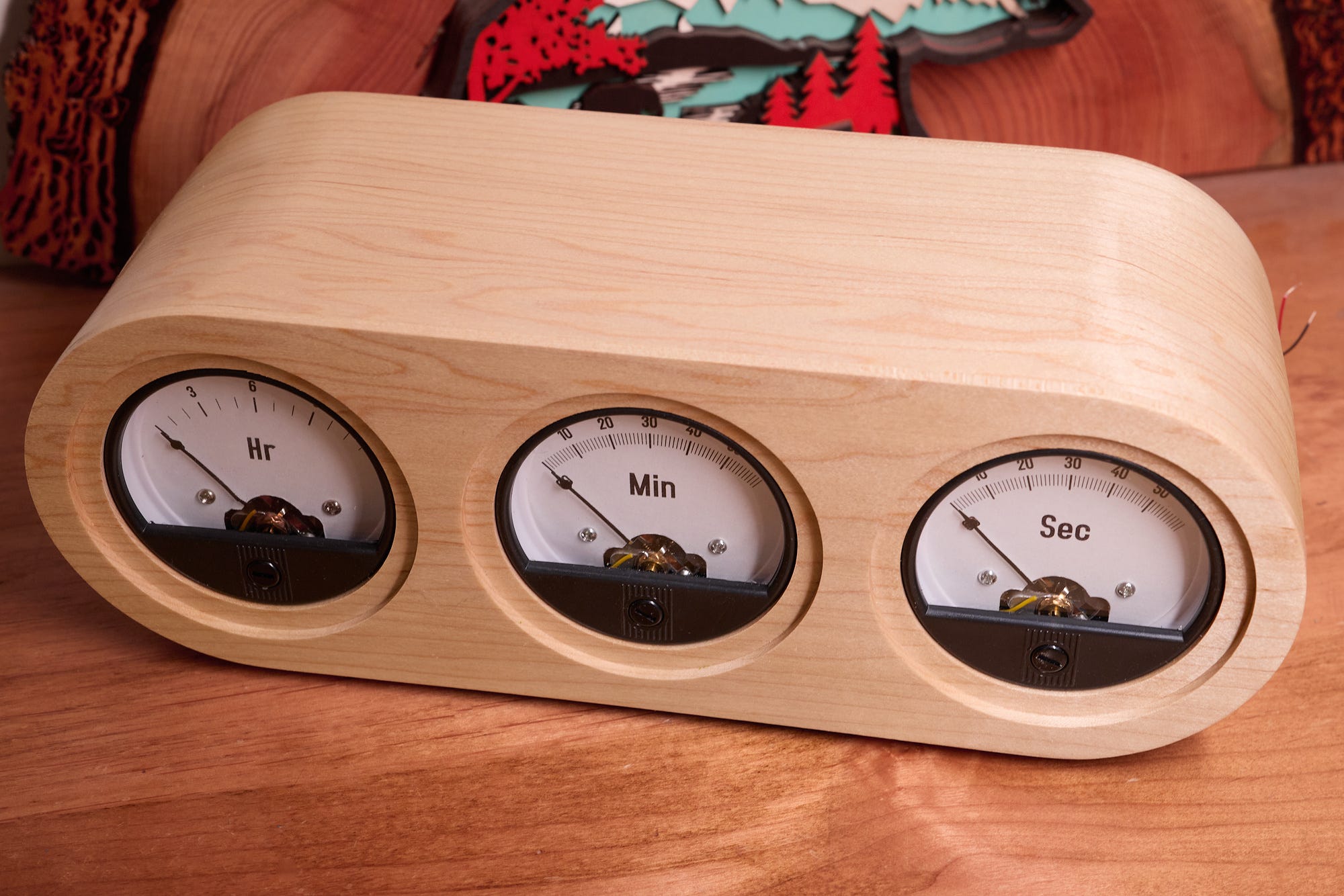
Not bad, right?
The circuit is far less interesting than the enclosure. It took an hour or so to put it together: I grabbed the venerable AVR128DB28 MCU, powered it off a wall wart, and interfaced it to an 8 MHz crystal (ECS-80-18-4X-CKM). A 32.768 kHz crystal would also work fine. The panels are connected to three digital output pins (PC0, PC1, PC2). Finally, two input pins (PD6, PD7) are interfaced to two small pushbuttons mounted on the back and used to set time.
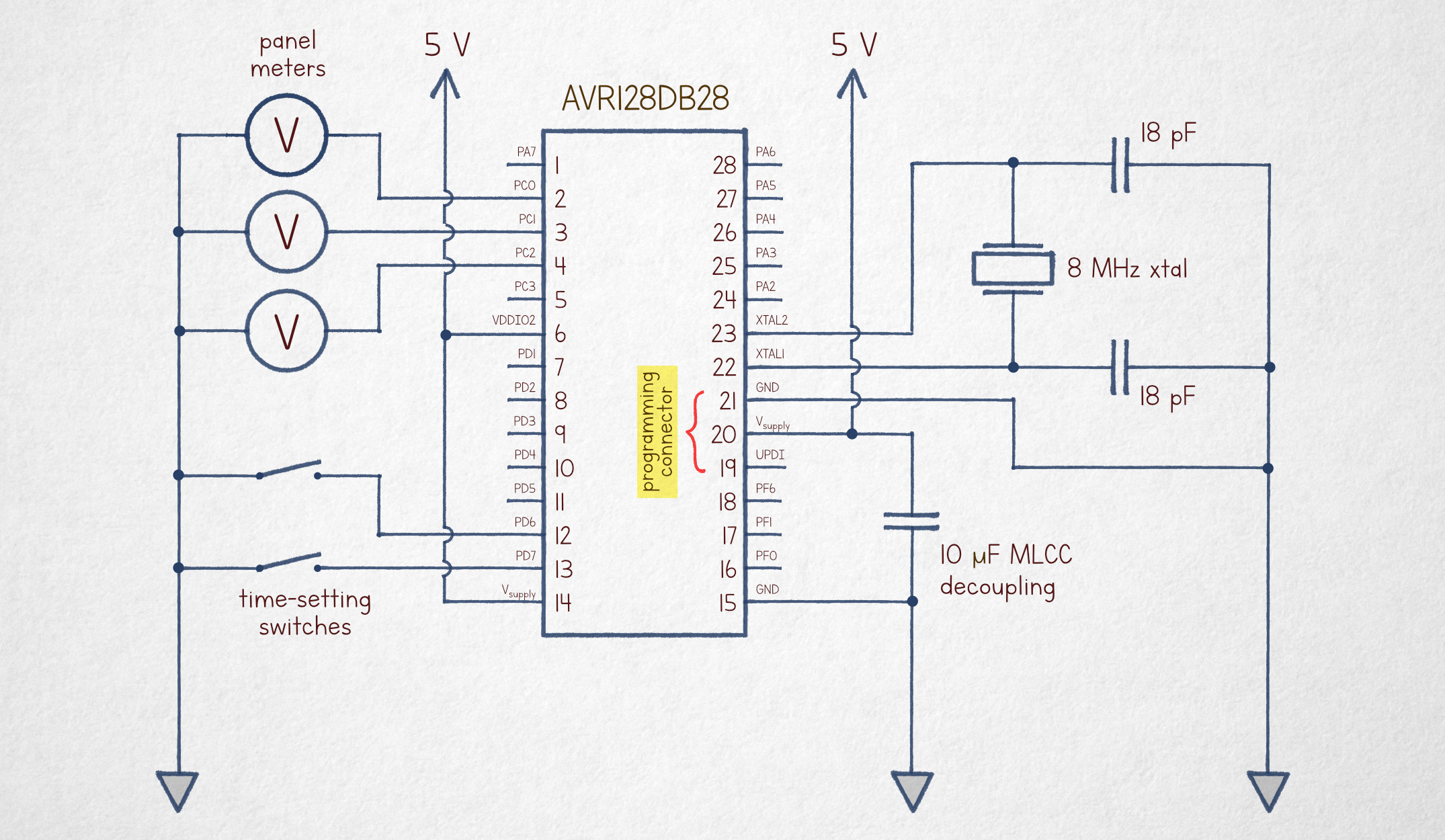
Note that the circuit doesn’t require digital-to-analog converters or any other additional components to drive the meters; I’m just using a relatively high-frequency, 1-bit digital pulse train. The inertia of the meter (and the inductance of the electromagnet coil) does the rest, settling in an intermediate position proportional to the software-controlled signal duty cycle.
The code can be viewed here; it’s short and well-commented. The basic idea is to advance a 10 Hz counter using a timer interrupt synchronized with the crystal. With this out of the way, the main event loop computes the appropriate duty cycle and then manually toggles the output pins. Although the chip has a hardware PWM module, the application is simple enough that using the PWM circuitry wouldn’t really buy us anything.
Here’s the obligatory “rollover” video captured around 11:59:59:
Peace out.
If you’re new here, you might enjoy some of my other articles:


Some postscripts, based on forum comments:
1) The dramatic drop and bounce are intentional. They would be trivial to compensate for in software, but it would make the clock a lot less interesting to watch.
2) You don't need protection diodes for the meter coils because it's a push-pull drive that is low impedance throughout the PWM cycle. Further, the current through the coil is trivial, the inductance is relatively low, and with the SRL=1 slew-rate limit, the MCU switching speed is to the order of ~40 ns, so even with on-off drive, there wouldn't be much of a voltage spike.
3) For internet sleuths: the earliest mention of a voltmeter clock that I could find is this 2007 article: https://makezine.com/article/maker-news/the-chronulator/
Cool project! For anyone interested in the square meters just search for “62C voltmeter”