Fear and loathing in the land of MCUs
Interfacing a bare-metal AVR microcontroller to an OLED display based on SSD1306 / SSD1309 - complete with a custom font.
As a kid, I loved to take things apart. Back then, consumer electronics hid a dizzying variety of components to salvage: relays, trimmer caps, rotary switches, logic gate ICs, and even the occasional vacuum tube. Sometimes, you’d come across a programmable chip with enough CPU power to operate a four-function calculator — but usually not more than that.
Today, powerful programmable microcontrollers (MCUs) and their system-on-a-chip brethren (SoCs) are slowly eating the world. Even in rudimentary applications, the convenience and flexibility of a tiny computer is hard to beat. If you want to blink some Christmas lights, grabbing an MCU takes less work than wiring up the ubiquitous 555 timer chip — let alone building an oscillator from scratch.
Some electronics old-timers see this as a cheapening of their craft. I disagree: analog circuit design is arcane art, and not every hobbyist has the stomach for it. If an artist can grab a Raspberry Pi to bring their creations to life, the world is better off, no matter what the gatekeepers think.
At the same time, flocking to “whole computer” solutions such as Raspberry Pi comes at a cost. Consider that many embedded applications — from sampling audio to driving a motor — need I/O to happen at precise and consistent intervals. Yet, in the Linux user space, there can be an unpredictable delay between writing to a filesystem object and seeing the outcome on an output pin. Other pitfalls await, too: for example, I’ve seen Linux SoCs malfunction due to the filesystem slowly filling up with temporary files or system logs.
In many cases, it’s simpler and cheaper to eschew Linux and develop your code on a “bare” chip. It might seem scary to have to write your own drivers for peripherals, but most of the time, the task is far simpler than it seems. To illustrate, allow me to walk through the creation of an OLED display driver for an Arkanoid-style handheld game covered in one of my earlier posts.
Prelude: the world of low-cost MCUs
When you take Linux off the table, you’re free explore a great variety of robust and affordable MCUs — from surprisingly capable 8-bit microcontrollers to beefy 32-bit devices ideal for memory- or bandwidth-intensive tasks.
It bears noting that in this context, “8-bit” doesn’t stand for blocky graphics, software that comes on cassette tapes, and 1980s hairdos. It’s simply that the circuitry is designed to manipulate data in 8-bit chunks; it follows that the addition of two 16-bit numbers might take two CPU cycles instead of one. On the flip side, the reduced complexity of the die makes the chips dirt cheap, tolerant of a wide range of supply voltages, and capable of driving substantial currents on their output pins.
Their other specs can be impressive too. Take the AVR128DB family of MCUs: with single-cycle execution and clock speeds up to 24 MHz, they are about 50 times faster than Commodore 64. Further, the dies are loaded with accessories such as analog-to-digital and digital-to-analog converters, configurable op-amps, pulse-width modulation drivers, uncommitted configurable logic arrays, comparators, zero-cross detectors, serial bus transceivers, and more. In essence, you get a software-defined electronics lab in a box.
That’s not to say that 8 bits is always enough: in applications requiring fast floating-point math or gobs of memory, 32-bit MCUs are worth the price. Microcontrollers based on the ARM Cortex-M architecture — say, the SAM S70 series — are available with clocks of 300+ MHz, yet remain surprisingly simple to boot up and use.
But for this particular handheld gaming project, I had no need for such luxuries, and an 8-bit AVR MCU proved to be the optimal pick. To understand how easy it is to hit the ground running on such devices, consider the following “hello world” example that flashes a connected LED:
#define F_CPU 1000000UL

#include <avr/io.h>
#include <avr/delay.h>

int main() {
  DDRA = 255;         /* Configure all pins of port A as outputs. */
  while (1) {
    PORTA ^= 1;       /* Toggle pin 0 of port A */
    _delay_ms(500);   /* Wait 500 ms */
  }
}
Much like in any Linux binary, there is a small compiler-inserted boot stub that does a bit of housekeeping and then passes the control to main(). DDRA and PORTA are macros that point to the microcontroller’s in-memory I/O registers: the first designates selected pins as either inputs or outputs; the second controls the voltage on said pins. Finally, _delay_ms() is a simple busy loop.
The external circuitry is minimal too: the MCU can be connected directly to two AA batteries or to a 5V wall wart. Programming and debugging is accomplished with a simple USB dongle wired to the designated pins. The dongle allows you to upload new programs or remotely step through your C code, inspecting variables and registers along the way.
Alright, that’s easy. But what if the goal is to drive an entire graphical display, rather than a simple LED?
Talking to SSD1306 / SSD1309
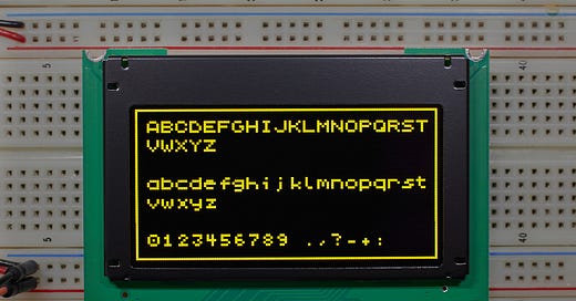
The centerpiece of my Arkanoid clone is a 128x64 pixel OLED module: Crystalfontz CFAL12864J-Y. If you look closely at any modern flat-panel display, you’ll notice that it comes with a tiny embedded controller, sometimes perched on the flexible polyimide cable leading to the unit. The controller’s job is to translate binary image data into a mess of analog voltages that need to be applied across hundreds or thousands of conductive lines that make up the screen. Some controllers might even have their own graphics RAM, permitting the computer to update the display at its own pace without having to race the dot clock.
The controller inside this particular OLED module is Solomon Systech SSD1306 / SSD1309. It supports two flavors of serial bus interfaces — I2C and SPI — as well as two types of parallel communications, known as “6800” and “8080”.
Most OLED drivers available on the internet use the I2C protocol, but this method is painfully slow, limited to a bit rate of about 1/16th the frequency of the CPU. If you take an MCU clocked at 1 MHz and factor in the protocol overhead, you’re looking at a full-screen refresh rate of 7 frames per second or less.
The SPI protocol fares better, with bit rates up to one half of the CPU clock. But the parallel mode is by far the best, moving multiple bits at once and offering peak bit rates higher than the frequency of the MCU itself. The gains are worth the effort: on a single-threaded microcontroller, near-instantaneous screen updates eliminate the need for messy state machines if you also need to accommodate other tasks, such as generating sound or actually running the game.
With the interface out of the way, I still needed to make a decision about the framebuffer. Most existing drivers use the memory on the SSD1309 chip for storing screen state, but this is a severe constraint: any updates must happen in 8-bit chunks, making it hard to fluidly animate sprites without clobbering objects nearby. Local framebuffer — at a modest price of 1 kB RAM — seemed a better choice.
The 8080 parallel interface
The “8080” interface is a common sight in embedded systems and works in a remarkably simple way. In its most basic write-only variant, it requires ten I/O lines: eight designated for data bits, a control line dubbed RS- (“register select”), and another labeled WR- (“write”).
To talk to a peripheral, the MCU sets the RS- line to indicate whether it’s about to issue a command (0) or send data (1). Next, the WR- pin is set low; a byte is presented on the data pins; and the WR- is moved back to high. The rising WR- edge triggers the requested operation on the peripheral’s side.
In other words, sending a command to the OLED is as simple as:
void oled_send_cmd(uint8_t cmd) {
  PORTB &= ~(1 << B_OLED_RS);
  PORTB &= ~(1 << B_OLED_WR);
  PORTA  = cmd;
  PORTB |= (1 << B_OLED_WR);
}
A full implementation of the interface would also make use of the RD- (“read”) line, which permits bidirectional communications; and the CS- (“chip select”) pin, which allows multiple peripherals to coexist on the same bus. But in my circuit, none of that was needed; I had CS- permanently tied low, and RD- tied high.
A disappointing property of the SSD1309 chip is that it doesn’t reset itself on power-up, so I also put the MCU in charge of the chip’s RES- (“reset”) line. This is used just once at startup; it would also be possible to strobe the line with a simple analog circuit — but again, it’s more work than hooking up the pin to an MCU.
The controller supports a considerable number of commands, but we only need a handful: to turn the display on and off (0xAF and 0xAE), to adjust contrast (0x81), and to change the addressing mode (0x20). Beyond that, we just keep sending full-screen updates of 128x64 pixels as “data” packets, with the device automatically wrapping around to x=0 and y=0 at the end:
void oled_update(void) {
  uint16_t i;
  PORTB |= (1 << B_OLED_RS);
  for (i = 0; i < sizeof(cur_screen); i++) {
    PORTB &= ~(1 << B_OLED_WR);
    PORTA  = cur_screen[i];
    PORTB |= (1 << B_OLED_WR);
  }
}
Controller memory organization
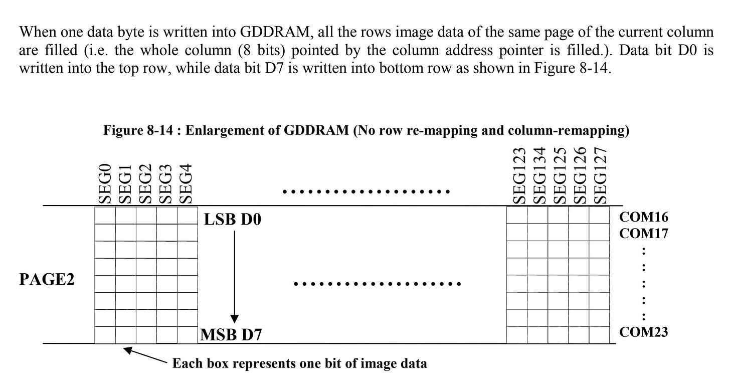
The SSD1309 framebuffer is organized into “pages”, each corresponding to eight adjacent, horizontal rows of pixels. Each page is further divided into 128 “segments” — vertical slices that are 1 pixel wide and 8 pixels tall.
In the default addressing mode, each byte received from the MCU fills one vertical 8-pixel segment; the segment pointer is then advanced to the right, awaiting the next byte. Once the last segment is complete, the page counter advances and the cycle repeats:
This design presumably simplifies text rendering using old-fashioned, HD44780-era 5x8 pixel fonts — but is utterly confusing for graphics of any sort. An alternative “vertical” addressing mode can be enabled on the chip, causing the page pointer instead of the segment pointer to advance after each byte. This more closely resembles the customary coordinate system used on computer screens, but the visuals are rotated 90° clockwise and flipped around:
To fix this mess, it’s necessary to apply translation in software. There are two possible routes: at read time, when sending the data to the display module; or at write time, keeping the MCU framebuffer in the native SSD1309 format and doing some translation magic whenever we’re asked to put something new on the screen.
In the end, the latter seemed like a more sensible choice: usually only a small portion of the framebuffer changes in between the refresh cycles, so less time is wasted if we can avoid constant full-screen recalculations along the way.
The code isn’t pretty, but at least the weirdness is contained to a single line:
#define set_pixel(_x, _y) do { \
    uint8_t _tx = (_x), _ty = (_y); \
    cur_screen[((_ty & 63) >> 3) + ((_tx & 127) << 3)] |= (1 << (_ty & 7)); \
  } while (0)
Adding text support
Unlike many LCD controllers of earlier vintage, the SSD1309 has no native support for text; if you want to say “hello world”, you better bring your own raster font.
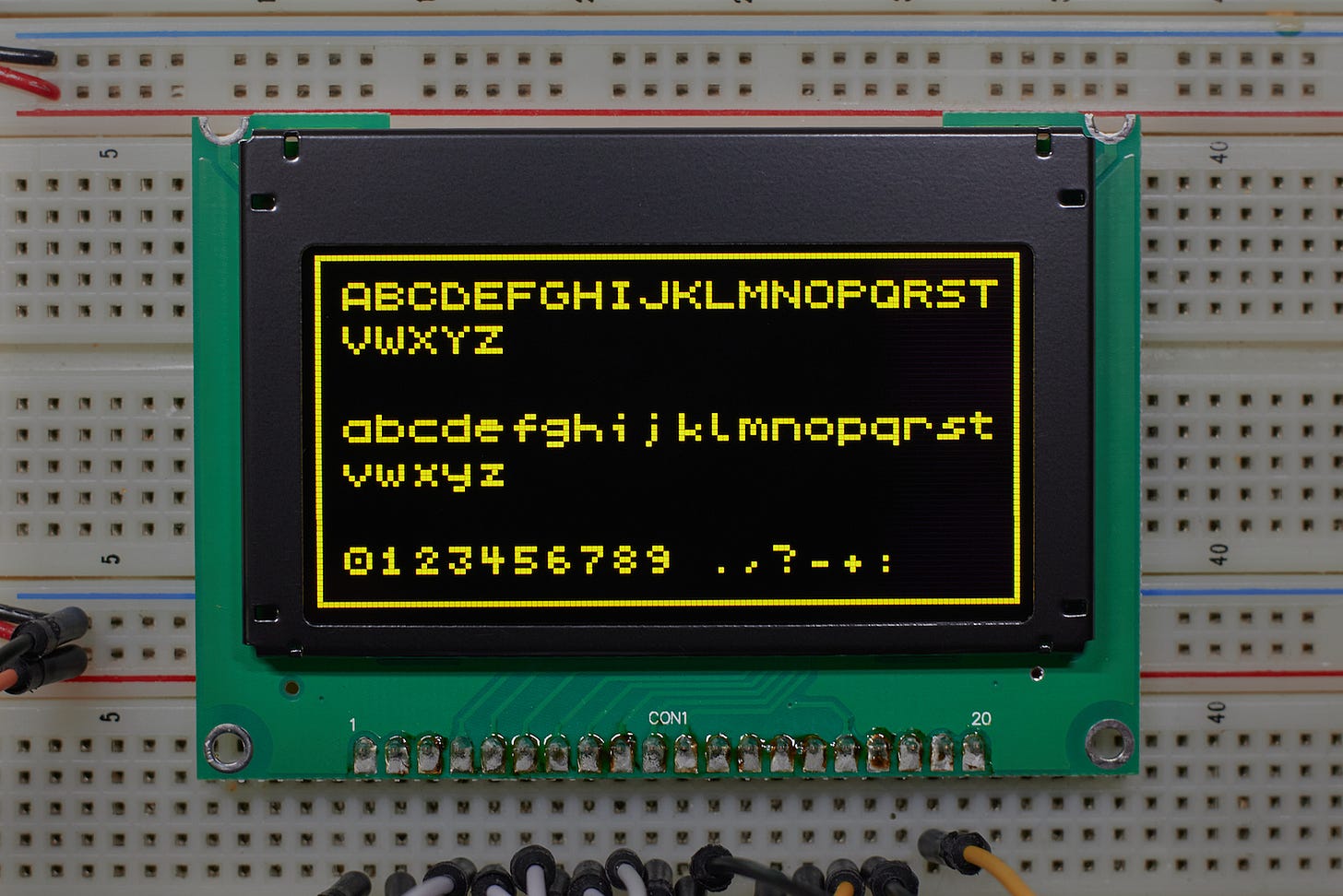
Of course, a graphics library that can’t easily output text on the screen is of limited use. I figured it’d be good to pair the driver with a 6x6 pixel typeface — a resolution that’s still perfectly legible, but lets me cram 21 columns and 10 rows of text onto that cute little 128x64 screen. Alas, despite a fair amount of online sleuthing, I couldn’t find a suitable ready-made font. Most “6x6” typefaces lacked any built-in spacing between adjacent letters. You could pad them manually, but that turned them into 7x7 , sacrificing quite a bit of screen real estate.
In the end, this was hardly a bother; I used to draw fonts by hand for “fun” back in the 1990s, and I still had the muscle memory to quickly crank out this spiffy ZX Spectrum-inspired choice:
Epilogue
The driver code I developed is simple, performant, and extensible — and despite having no prior experience with OLEDs, I was able to crank it out in a day.
That’s not to pooh-pooh Raspberry Pi and its ecosystem; it’s just that sometimes, a simpler platform is a smart choice, and I’m hoping to make my fellow hobbyists a bit less afraid of such alternatives.
👉 For the second installment of the series — a dive into the SPI bus — click here. For a more advanced gaming demo, check out Sir Box-a-Lot. To review the entire series of articles on electronics, check out this page.
I write well-researched, original articles about geek culture, electronic circuit design, and more. If you like the content, please subscribe. It’s increasingly difficult to stay in touch with readers via social media; my typical post on X is shown to less than 5% of my followers and gets a ~0.2% clickthrough rate.


Any recommendations for a simple camera to connect to one of these? It doesn't need to be color or have a high frame rate.