Making sense of surface-mount components
So you're designing an SMD PCB. Which of the hundreds of resistor, capacitor, and IC sizes do you need?
In an earlier article, I professed my love for old-fashioned perfboards and through-hole prototyping. I use this approach because it lets me progress from an idea to a reasonably durable prototype in a single afternoon. In contrast, the use of surface-mount parts means fiddling my thumbs for 1-2 weeks while made-to-order printed circuit boards (PCBs) are in the mail — and that’s if I get the layout right on the first try.

That said, past the prototype stage, the shortcomings of this approach are plain to see: hand-wired perfboards take a long time to build, don’t look very professional, and are difficult to debug. Nowadays, mail-order PCBs cost as little as $2 a piece, so there’s little reason not to upgrade your designs down the line. And although it’s possible to continue with through-hole technology (THT), surface-mount parts (SMD) tend to be more compact, more abundant, and about as easy to use.
In this spirit, back in March, I posted a short introduction to the process of designing your own PCBs. Today, I’d like to take a stab at one of the lingering sources of PCB anxiety: the dizzying variety of surface-mount package sizes. In the world of through-hole components, almost every part has a familiar footprint. When it comes to SMD, DigiKey stocks about 100 different form factors for resistors alone.
Passives and friends
Many small, two-terminal components — from resistors, to ceramic capacitors, to LEDs — come in rectangular packages in a 2:1 aspect ratio, with solder terminals along the shorter edges. The four most commonly encountered sizes are:
1206, aka 3216 metric (3.2×1.6 mm). This is about half the size of a typical through-hole resistor. The parts in this form factor are large enough to be soldered by novices with no special training. There is no need for magnification or a precision soldering station, although good tweezers are a must. Resistors in this size are usually rated to 1/4 W.
0805, aka 2012 metric (2.0×1.25 mm). This is an intermediate form factor that offers considerable space savings while still being fairly easy to hand-solder. Along with 0603 (below), it’s one of the two most common sizes encountered in commodity electronics whenever space is not at a premium. Resistors in this size are usually rated to 1/8 W.
0603, aka 1608 metric (1.6×0.8 mm). Half the size of 1206. Small enough to fly away if you sneeze in its general direction. Exhibits a lot of static cling too. A moderate challenge for hand-soldering; fine-tip soldering irons are advisable. Resistors of this variety are typically rated to 1/10 W.
0402, aka 1005 metric (1×0.5 mm). Tricky to handle, about the limit of what can be hand-soldered by most hobbyists. Because of the need for precise alignment and the difficulty of inspecting joints with the naked eye, 0402 components benefit from a stereo microscope. Resistors of this kind are usually rated to 1/16 W. Frequently encountered on smaller or more densely-packed boards, including computers.
You can find larger or smaller sizes, but there usually needs to be a reason for their use. For example, passives as small as 01005 (0.4×0.2 mm) can be found in smartphones and wearables. That said, such tiny parts pose challenges not only to humans, but even to pick-and-place machines, so their use is limited.
When it comes to selecting the right size for your project, a good rule of thumb is that larger packages will have better DC characteristics. For example, as noted above, 1206 resistors will have higher power dissipation ratings; meanwhile, capacitors will exhibit lower ESR, higher operating voltages, and less of the dreaded voltage-dependent capacity loss inherent to MLCCs.
On the flip side, larger components typically perform worse on the AC front. Increased physical dimensions mean more stray inductance or capacitance. This is seldom a big issue in hobby applications, but as you approach the gigahertz territory (or more precisely, sufficiently high signal rise and fall times), smaller components tend to be a better choice.
Barring any constraints of this nature, 1206 is a good “starter” size for your first project, and a reasonable all-around choice if your design is only using a handful of passives. On more crowded boards, 0805 is a better default.

Integrated circuits
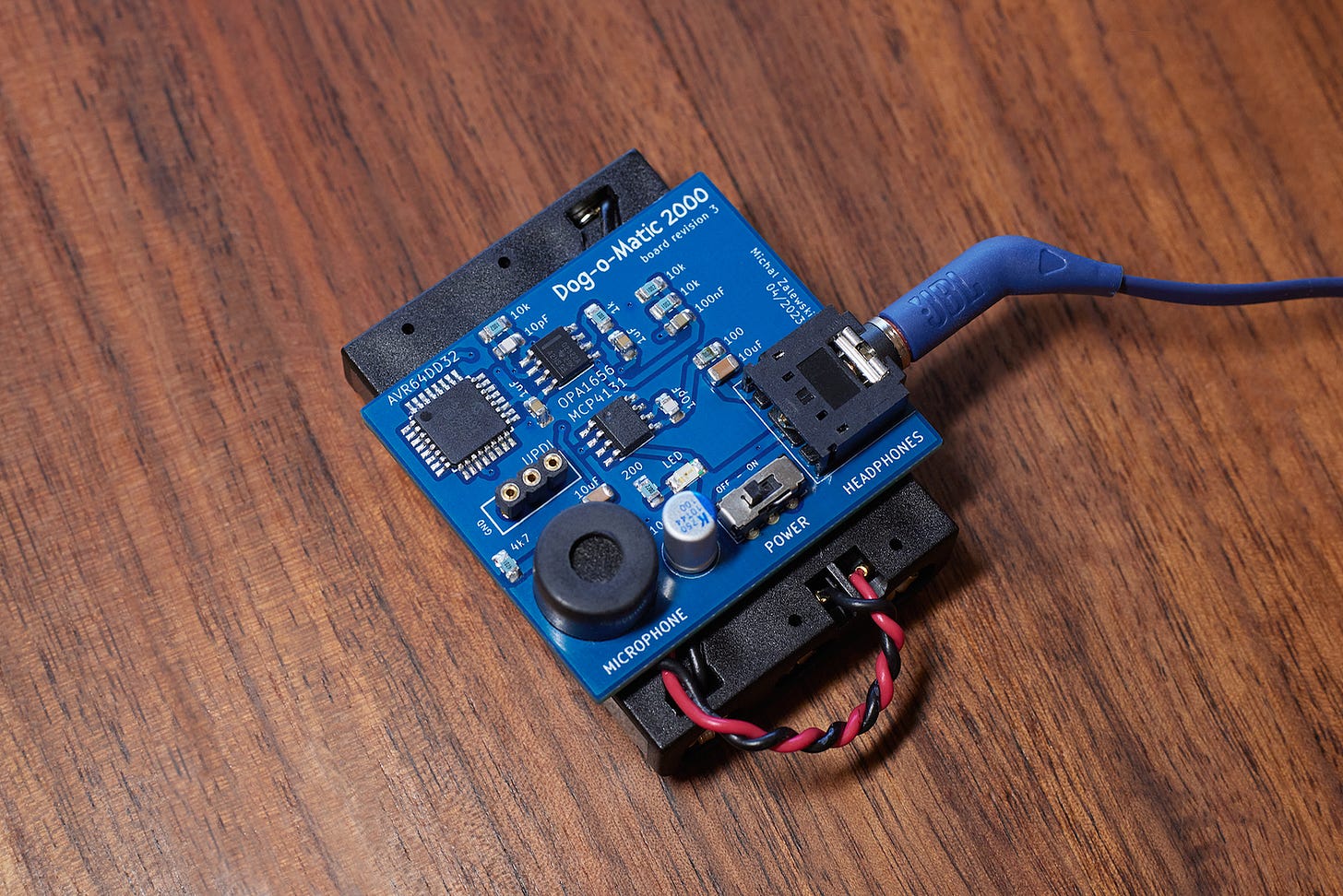
Many chips with low pin counts — including most op-amps and 8-bit microcontrollers — are available in rectangular SOIC or SSOP / TSSOP packages with pins arranged along the two longer edges. The first size — SOIC — is trivial to work with: it has 1.27 mm lead spacing, exactly half of what’s used for through-hole parts. The other form factor — SSOP / TSSOP — is more challenging. With typical spacing of around 0.65 mm, it calls for a good soldering iron and a keen eye to spot bridged pins. That said, with a good technique and a generous use of flux, the package can be tamed.
Integrated circuits with higher pin counts, including some 8-bit and most 32-bit MCUs, might also come in square packages leads on each side; these devices are designated as QFP, TFQP, or LQFP. Although lead spacing varies, it’s most common to see 0.5 mm. Such chips can be soldered by hand by an experienced user, but they greatly benefit a stereo microscope to ensure proper alignment and to examine the result. Because the gap between the leads is only about 0.25 mm, it’s easy to accidentally bridge pins.
That’s not to say that these quad 0.5 mm packages need to be avoided; it’s just that they call for a specific toolkit. Some practice on scrap parts or “training” boards is advisable too.
In addition to the aforementioned packages, there is a range of chips with no exposed leads. The designations include BGA, DFN, QFN, WLP — and as a rule of thumb, almost any other acronym you don’t immediately recognize and that isn’t a riff on “SOP”, “SOIC”, or “QFP”. These packages are meant for applications where space is at a premium, or where pin counts are so high as to make QFP packaging impractical. Such ICs can be still soldered at home using stencils and hot air stations or makeshift reflow ovens, but the results are difficult to inspect or repair. In other words, leaded packages are almost always a better pick.
Other components
Some components, such as power inductors, connectors, switches, or discrete transistors, will have different packages; only some of these are standardized. That said, the earlier observations about part size and lead spacing are still applicable. For example, FFC (flexible flat cable) connectors with 0.5 mm lead spacing — commonly used for LCD panels — will be about as challenging to solder as an LQFP-64 chip. Similarly, SOT-23 transistors, roughly similar in size to 1206 passives, will be easy to work with; while the diminutive SOT-523 package, dimensionally similar to 0603 resistors, won’t be too much fun.
There is also a range of components where through-hole mounting is still preferable, or where surface-mount variants offer no size or cost advantages. An example of the former are toggle switches and audio jacks; in both cases, through-hole installation improves mechanical strength. As for the latter, a good example are electrolytic and aluminum-polymer capacitors: the can is the same size, whether you’re using wire leads or solder pads. In such situations, you shouldn’t feel that you have to pick SMD, and there’s no shame in falling back to the old ways.
👉 For other articles on electronics, click here.
I write well-researched, original articles about geek culture, electronic circuit design, and more. If you like the content, please subscribe. It’s increasingly difficult to stay in touch with readers via social media; my typical post on X is shown to less than 5% of my followers and gets a ~0.2% clickthrough rate.

