MCU land, part 9: ST7789, the final frontier
A step-by-step demo for hooking up ST7789-based LCD displays to a microcontroller. No OS and no drivers required.
In some of my earlier articles dealing with “bare metal” microcontrollers, I talked about the process of interfacing them to modern graphic display modules. This task remains a bit of a mystery to hobbyists: there are few tutorials dealing with anything more modern than the text-based HD44780 LCDs from the 1980s. When graphics are needed, it’s common to reach for a Linux-based system-on-a-chip, or to rely on questionable third-party libraries that use the woefully slow I2C protocol.
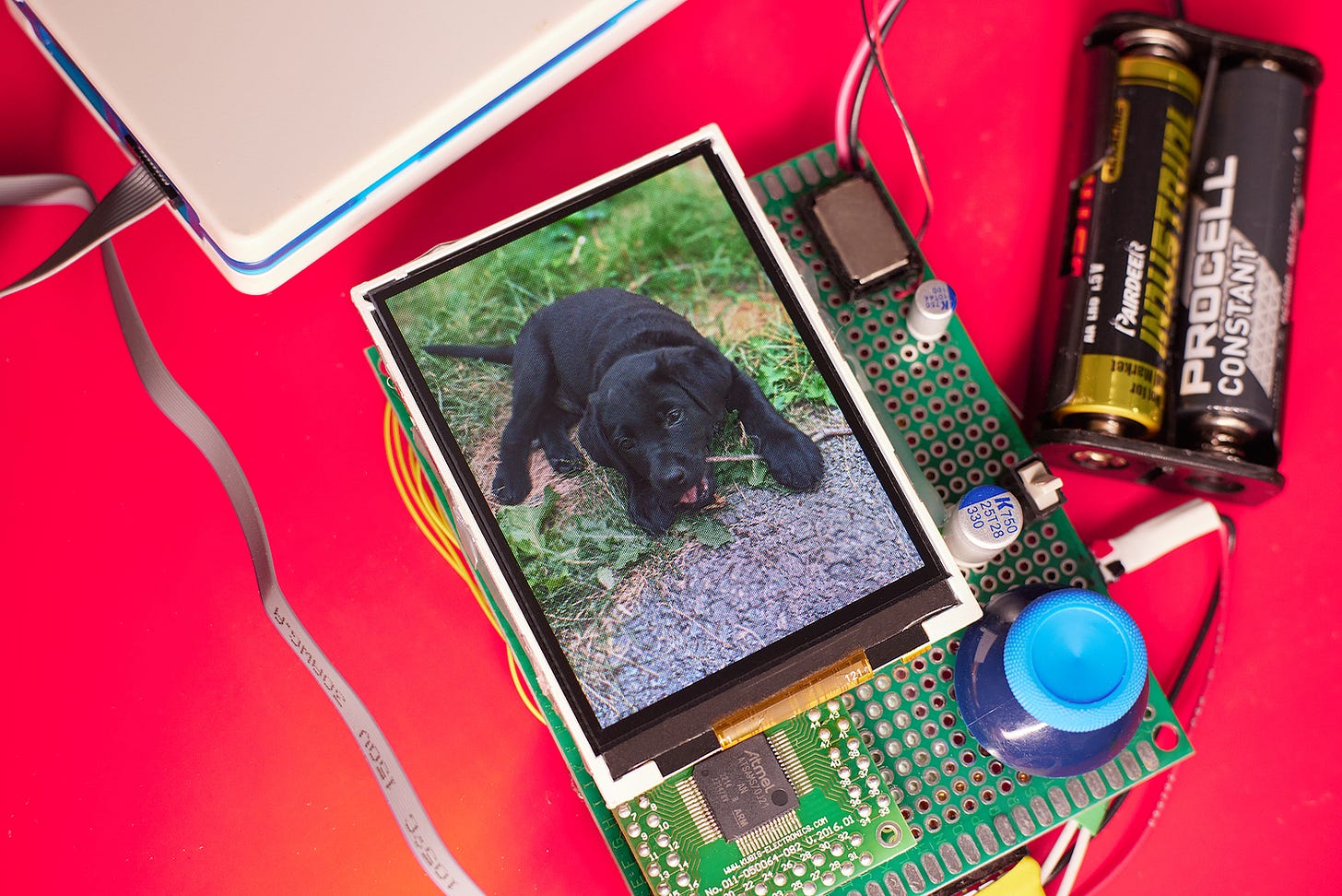
On the heels of the tutorials for 128x64 monochrome and 160x128 full-color OLED modules, I’d like to share a quick note about the surprisingly painless task of driving a beautiful 2.8” 240x320 IPS panel from Newhaven Display (NHD-2.8-240320AF-CSXP-F) with a Microchip SAM S70 (aka PIC32CZ CA70 / MC70) Cortex-M7 MCU.
This particular display unit is equipped with a ST7789Vi controller. There are no tutorials and virtually no working implementations to look at; the code provided by Newhaven in their spec goes through dozens of unnecessary and poorly-explained steps, only to stop short of actually displaying an image. In light of this, I was bracing for hours or days of debugging — but the project turned out to be by far the simplest of all the examples discussed in this blog so far:
The hardware uses a a modified implementation of the generic “8080” bus with 16 data lines and two essential control lines: D/C (for switching between data and commands) and WR- (bus timing, triggered on rising edge). I talked about the bus in the article on SSD1306 / SSD1309 display controllers, but a recap fits on a napkin: you select between commands and RGB data by asserting the D/C line, and then toggle WR- to transmit. The write cycle for this particular display is 66 nanoseconds, so the maximum bus speed is around 15 MHz — resulting in a data rate of 240 Mbit/s.
As noted earlier, the reference implementation from Newhaven spends time tweaking voltages, timing, and gamma tables, but none of this is necessary to get the display to a usable state. The defaults are sensible and the minimal sequence of steps is as follows:
Perform a hardware reset by pulling the RESET- line down for a brief while. This gets all the ST7789 registers in a predictable state.
The display boots up to a power-saving mode, so send command 0x11 (SLPOUT) to enable normal operation.
Send command 0x3A (COLMOD) followed by data byte 0x05 to configure a 16 bpp (65k colors) display mode. It is also possible to use 18 bpp (262k colors), but this is less efficient, and perceptual differences are minor.
Send command 0x21 (INVON) to enable the color inversion mode that is necessary for in-plane switching (IPS) TFT displays.
Send command 0x29 (DISPON) to turn the display on.
Send command 0x2c (RAMWR) to enter memory write mode, then start sending 16-bit pixel values for the image.
In contrast to most other displays discussed earlier, there are no bizarre addressing schemes or other hoops to jump through. The 16 bpp color mode is perhaps the only curiosity: it is known as RGB565, and uses 5 bits for the red component, 6 bits for green, and 5 bits for blue.
The generation of compliant image data is not hard; the path of least resistance is to prepare a normal 240x320 JPEG or PNG image, then use ImageMagick to extract raw 24 bpp pixel values to a separate file:
$ convert image.png image.rgbThe RGB triplets in the intermediate file can be then read to compute 16-bit pixel values, like so:
#define RGB16(_r, _g, _b) \
  ( (((_r) >> 3) << 11) | (((_g) >> 2) << 5) | ((_b) >> 3) )
For a complete demo, including a conversion tool, see this link. On the aforementioned Microchip’s SAM S70 MCU (ATSAMS70J21B), the code is capable of achieving ~200 fps when doing full-frame updates, or proportionately more when redrawing just a portion of the screen.
Driving the display from an 8-bit MCU would be similarly easy; the reason I upgraded this project to a 32-bit chip is simply a matter of memory: for the handheld game I’m aiming to build, I need to store a good number of full-screen bitmaps in the on-chip flash.
Full-color TFT displays with parallel interfaces are available up to 640x480 or so; past that point, it becomes expensive to maintain sufficient framebuffer memory on the controller, and dot-clock interfaces become more common. Finally, some of the highest-resolution panels usually depend on quasi-proprietary protocols such as MIPI or LVDS — and require dedicated graphics hardware to drive. Still, for most embedded applications, 320x240 is plenty of screen real estate.
👉 For more articles on MCU programming and display interfaces, see this list.
I write well-researched, original articles about geek culture, electronic circuit design, algorithms, and more. This day and age, it’s increasingly difficult to reach willing readers via social media and search. If you like the content, please subscribe!

