
Choosing an op-amp for your project
Just say no to LM741 and LM324 / LM358.
This article assumes some familiarity with the principles of op-amps; if you need to jog your memory, start with an earlier write-up on signal amplification.
The most common design paradigm for analog circuits is copy-and-paste. I’m not judging: simple analogies don’t adequately explain the behavior of transistors and op-amps, while academic textbooks are inaccessible to hobbyists and even some pros. When you just want the job done, the path of least resistance can be to look at someone else’s work.
That said, for op-amp circuits, the consequences of this habit have gotten comical. The internet is brimming with obsolete designs that rely on UA741 / LM741 — a Cold War relic developed in 1968. The chip’s 1970s siblings — TL071 and LM324 / LM358 / LM2902 — are close second on the list. To make things worse, this peculiar status quo is now being propped up by AI slop in the mold of “top 10 op-amps (updated for 2025)”.
In reality, the amplifier technology has progressed dramatically in the past fifty years; modern-day chips behave more predictably and are easier to use. For example, they’re free of the input voltage constraints of LM741, or the phase reversal and crossover distortion issues in LM324:
To cut to the chase, if you’re designing a new op-amp circuit, here are some decent, all-around alternatives made in the 21st century that are well-suited for single-supply applications:
Microchip MCP6272: 2 MHz bandwidth, RRIO, 2 - 6 V, 25 mA
Microchip MCP6022: 10 MHz, RRIO, 2.5 - 5.5 V, 20 mA
Texas Instruments OPA2323: 20 MHz, RRIO, 1.7 - 5.5 V, 110 mA (⭐)
Texas Instruments TLV3542: 100 MHz, RRIO, 2.5 - 5.5 V, 100 mA
Texas Instruments OPA2356: 200 MHz, RR output, 2.5 - 5.5 V, 60 mA
The first two chips are available in through-hole (PDIP-8) packaging. The rest comes in SOIC-8, a user-friendly form factor that can be easily soldered to inexpensive breakout boards. I don’t have any stake in making these recommendations; I just think they’re reasonable, low-cost picks.
If I have your attention, keep reading for a quick summary of what to pay attention to when choosing a general-purpose amplifier IC.
Basic DC characteristics
The most fundamental parameter of an op-amp is its supply voltage range, followed by the maximum output current. These parameters are usually noted at the very beginning of the datasheet. In some battery-powered circuits, the amplifier’s “idle” (quiescent) current will be of interest too.
That said, this is not where the story ends. Many of the early devices required signals to stay well clear of the supply rails; for example, LM741 demanded about 2-3 V of headroom. Signals that didn’t conform to that spec would be clipped or worse; because of this, the ICs were commonly powered by awkward dual supplies — for example, ±15 V in a circuit that would have otherwise just needed +5 V.
Today, there is a wide selection of op-amps that work well in single-supply 3.3 V or 5 V circuits. Many mid-range devices can output a full range of supply voltages, usually just 20 to 100 mV shy of the supply rails. Such devices are known as rail-to-rail output (RRO). If in doubt, look at the “output swing” or a similarly-sounding parameter in the datasheet.
In the same vein, quite a few devices accept input voltages that extend a bit below the lower rail; some can also go slightly above the upper supply voltage. This reduces the need for awkward biasing and should be denoted in the “common-mode input range” field in the datasheet. An op-amp that combines full-range input and output is described as having rail-to-rail I/O (RRIO).
I should note that there is a small price to pay for this convenience. The most common internal design to achieve rail-to-rail input involves two complementary input stages — e.g., p-channel and n-channel FETs. One of the stages handles the bulk of the input range, but the other one takes over near the positive supply rail. Because of manufacturing constraints, the stages can’t be matched perfectly, so there tends to be a slight shift in the input offset (VOS) when the common-mode input voltage crosses the handover point:

It’s luck of the draw: when ordering the same part, you might a chip where the jump is ~0 µV, or where the difference is a high as 1 mV. Depending on what you’re doing and how much of an input range you need, big jumps can hurt linearity, especially in high-precision instruments that measure absolute voltages. Luckily, some of the latest op-amp designs — such as the aforementioned OPA2323 — use a built-in DC-DC converter (a charge pump) to generate a higher internal reference voltage. This eliminates the need for the complementary stages and makes the offset discontinuity go away.
Most of the time, op-amps are used with Vin+ and Vin- at roughly the same voltage; some devices add this as an explicit input constraint. For example, OPA1656 has protection diodes on the input terminals, so the pins become a short-circuit if the voltage delta exceeds about ±600 mV:

That said, most devices — including the chips recommended earlier in the article — should be free of this limitation.
Input stage: FET vs bipolar
Standard op-amps come with two basic types of inputs: bipolar and field effect (FET). Because the behavior of FET inputs is more intuitive, and because such chips are becoming dominant, I recommend sticking to that option unless you have a specific itch to scratch.
The key selling point for FET input stages is that they have a consistently high (gigaohm+) impedance at DC, eliminating some of the gotchas of bipolar designs. The trade-off is that in common with discrete field-effect transistors, the inputs have some non-trivial capacitance — usually around 2-4 pF. At higher frequencies, the effects of this capacitance might need to be taken into account. At that point, you probably also need to watch for parasitics on the PCB and in the feedback loop.
In contrast to FET, bipolar input stages have a somewhat high (megaohm) impedance only to the ground (ZICM). The impedance between the input legs (ZID) is lower, so if the Vin+ and Vin- voltages diverge, a measurable current can flow; this differential impedance can be low megaohms to kiloohms.
On the flip side, bipolar op-amps can have lower input capacitances, which can be a perk when dealing with high signal speeds.
Frequency response
The most important AC parameter of an op-amp is known as bandwidth gain product (fGBP or fGBWP). Most standard devices are designed to have an internal gain (AOL) that rolls off proportionally to signal frequency. At fGBP, this gain is reduced to one:

The nature of differential gain is often mischaracterized in introductory articles. As discussed earlier, op-amps don’t care about the absolute input voltage or the relationship you’re trying to maintain between any single input pin and Vout. In theory, such “single-ended”, non-differential gain (e.g., Vout = Vin+ · n) is free and can be arbitrarily high.
In practice, in the specific case of a conventional voltage-to-voltage circuit with two feedback resistors, the maximum attainable signal gain is (mostly) equal to fGBP divided by the input frequency; the reasons for this are pretty interesting and are covered in the aforementioned article. If that’s the architecture you’re building, the IC should be chosen to maintain sufficient gain at the intended signal frequency. Some headroom is good to minimize signal distortion, but unchecked excess is ill-advised: fast op-amps consume more power, tend to have more noise, and so on.
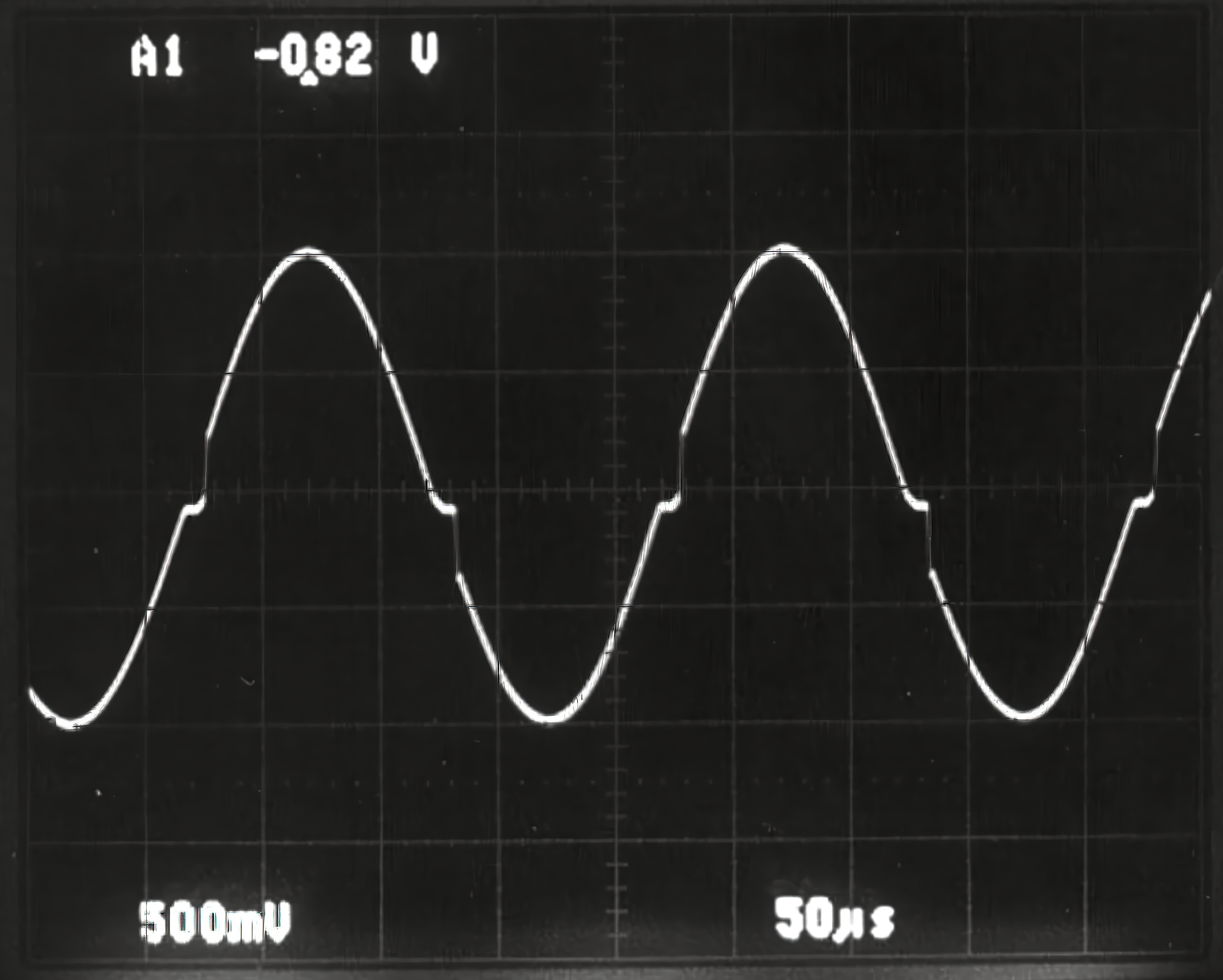
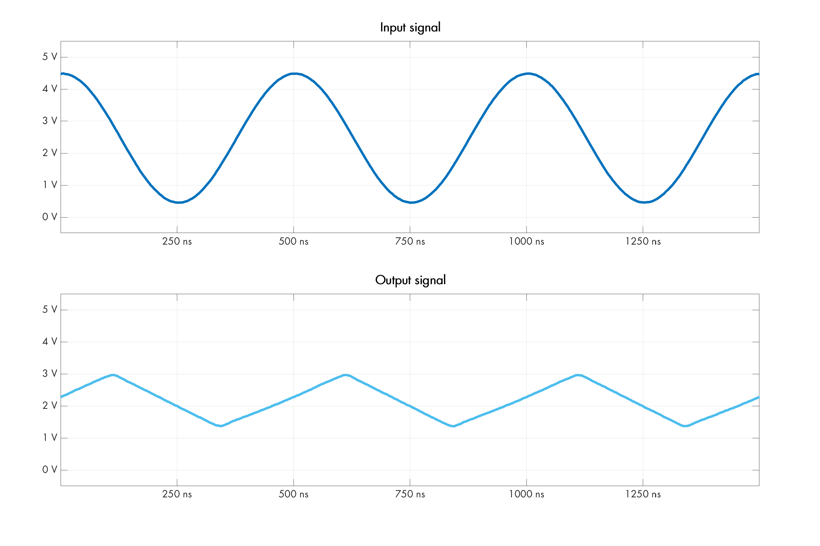
A secondary frequency consideration is the amplifier’s slew rate: the maximum rise and fall time for the output voltage. It is given in units such as V/μs and it should be cross-checked against the desired output swing at the highest expected signal frequency. If the rate is too low, the output may be unexpectedly distorted or attenuated. The effect of hitting the limit is shown below:
A related characteristic is the overload recovery time: the parameter describes how long it takes the output stage to bounce back from being driven all the way into the supply rail. Depending on the design of the amplifier, this can be anywhere from 2× to 100× slower than the chip’s normal response time; in modern FET chips, it’s typically closer to the lower bound.
Mostly overblown: internal noise
The performance of FET amplifiers is typically dominated by two types of noise: low-frequency “flicker” fluctuations due to random shifts in transistor bias currents; and broadband thermal noise that is evenly distributed throughout the chip’s frequency range:
The funky nV/√Hz unit in this plot is “noise density”; if you’re curious what it means and why it has such a weird unit, check out this followup article. Otherwise, the rule is simple: to get the RMS noise voltage, you can multiply the figure by the square root of the bandwidth the circuit is passing through. For example, if a chip is specified to have eN = 5 nV/√Hz and your design bandwidth is 100 kHz, the RMS noise works out to ~1.6 μV. The peak-to-peak value is technically unknowable — but in practice, you can get a good approximation of what’s going to show up on the oscilloscope screen if you multiply the RMS number by 6.
This empirical model is input-referred: that is, it’s what you’d see if you had a hypothetical voltage noise source piggybacking on the input of an ideal amplifier. In a standard voltage-to-voltage architecture, the calculated noise is amplified roughly in line with the resistor-configured signal gain. In transimpedance (current-to-voltage) circuits, noise amplification is inconsequential near DC, but eventually peaks at higher frequencies because the input capacitance forms a voltage divider with the feedback resistor — effectively adding “parasitic” voltage gain.
The reason all of this usually amounts to navel-gazing in hobby designs is that most modern op-amps have pretty good noise specs, often in the ballpark of 10 nV/√Hz for frequencies above 1 kHz. This is less than the thermal noise contributed by a single 10 kΩ resistor. In other words, unless you go to great lengths to keep other noise sources in check, op-amp performance on this front is seldom a major concern.
To be fair, as hinted earlier, low-frequency flicker fluctuations tend to be markedly worse in high-speed (100 MHz+) amplifiers, such as TLV3542 or OPA2356. It follows that if you’re interested in low-frequency signals, slower op-amps are a better pick. In sensing applications where near-DC drift can’t be tolerated at all, specialized flicker-compensated (“zero-drift”) devices — such as OPA2388 — are also worth a try.
Stuff not to worry about
Despite what content-farmed articles imply, most of the other parameters in the spec can be usually glanced over. For example, the DC value of open-loop gain (AOL) is almost never of real consequence. Roughly the same goes for input offset voltage (VOS): even in high-precision instruments, the absolute value is less important than the nearly-inevitable drift in response to temperature and time.
In any case, the parameters are usually poorly-characterized and vary from one specimen to another. In other words, if you’re building a sensitive instrument that measures absolute voltages — and if you can’t opt for an internally-compensated zero-drift chip — you will either need to calibrate the circuit for each new IC and then compensate for temperature changes; or employ automatic adjustment strategies such as periodically disconnecting the op-amp from the signal source and connecting inputs to a known reference to measure the offset.
Other characteristics can be important, but don’t vary much from one design to another within its class. In particular, modern op-amps have pretty decent supply ripple rejection ratio (PSRR) and good common-mode voltage rejection (CMRR) — with the earlier caveat about RRIO crossover artifacts.
If you liked this article, you might also enjoy:


For further articles about electronics, click here.
I write well-researched, original articles about geek culture, electronic circuit design, algorithms, and more. If you like the content, please subscribe.
Since this made it to HN an Hackaday, I'd like to address several quips from folks who I think just skimmed the beginning of the article.
1) Supply voltage: if you have a circuit that uses higher voltages, the picks mentioned at the beginning obviously don't work! I am recommending these ICs because 95%+ of contemporary designs are single-supply 3.3 V or 5 V circuits. If you need more range, there's plenty of modern chips that fit the bill and work better than LM741 & co. For example, OPA1656 is great.
2) Cost: the ICs mentioned at the beginning are inexpensive, but they're not the cheapest op-amps out there. They're just balanced picks with good specs. If you need the lowest possible price, you're still better served by a 21st century design. This may include slower but dirt-cheap options such as MCP6006, or redesigned versions of the vintage chips - e.g., LMV324A.
3) If it works, it works: sure. I'm not saying you have to switch if you have a drawer full of LM324 and it happens to work for you. But in practice, the internet is full of posts from people trying to make sense of crossover distortion, phase reversal, or signal voltage limitations of these old chips. They're just not very good op-amps, and novices should probably stay away.
Designing a quality and precise analog circuit is truly challenging. A few months ago, around September, I've been asked if I could make a controller for a fertilizer mixer. At a first glance - nothing fancy, just a pair of PID regulators for EC / pH each.
From the perspective of this project I can tell, that designing the right analog measuring circuits is a state of art. It is not only limited to selecting the right op-amps (most of the important factors You have nicely described above), but also many different aspects of the analog design.
As an example, the EC/pH probes are extremely high impedance devices, so using JFET op-amp is a must. But that's not all. I've learned the hard way, that EC/pH measuring circuits cannot be supplied with power from a same source. The electrodes of the probes not only have their high impedance [GigaOhms], but also own potential, and if they are put together into a conducting liquid, the currents start flowing in between probes rendering circuit readings unreliable.
Then, my second idea was to use a micro DC/DC inverters like TBA 1-0512E from Traco. It didn't work out either. The readings were unstable as before... despite measuring circuits were separated! Then, by using DSO I found a nice DC freewheeling diode ripple noise on the power line. By reading carefouly datasheets, I've learned Tracos have 100[mV p-p] ripple noise, where - i.e. the pH probe generates in between of -177..177[mV]. So yet another fail.
And I have mentioned, the circuits have to be separated. Then how to separate the analog circuits from the digital one? Either by converting Voltage-to-Frequency or by ADC converters that use isolated power lines, like AD7793.
Making long story short, after several months of hard work I am getting 0,7% of accuracy from the designs I have, and I believe I could do better in several aspects. Mainly that's the reason quality, industrial-grade analog products are pricey - and perhaps, in this very case I should go for the EC/pH transmitter device instead of reinventing the wheel.
Some could say that my words are sort of abstraction, because there are EC/pH meters on the market for a dozen of bucks to buy. Not gonna start my rant on them, let's say buying a six-pack would be a better use.