MCU land, part 10: blocks all the way down
Building a top-notch 32-bit game on a bare-metal ARM Cortex-M chip hooked up to an ST7789 IPS LCD module.
Back in January, I kicked off a series of microcontroller-themed articles by showing off a couple of basic handheld games that I built with my kids. A bit later, I followed up with a more ambitious project to revive a block-pushing classic on an 8-bit MCU interfaced to a full-color OLED display. In an era of Raspberry Pi everywhere, I wanted to illustrate the ease of building non-trivial apps on bare-metal platforms — with no operating systems, no drivers, and no third-party libraries to get in the way.
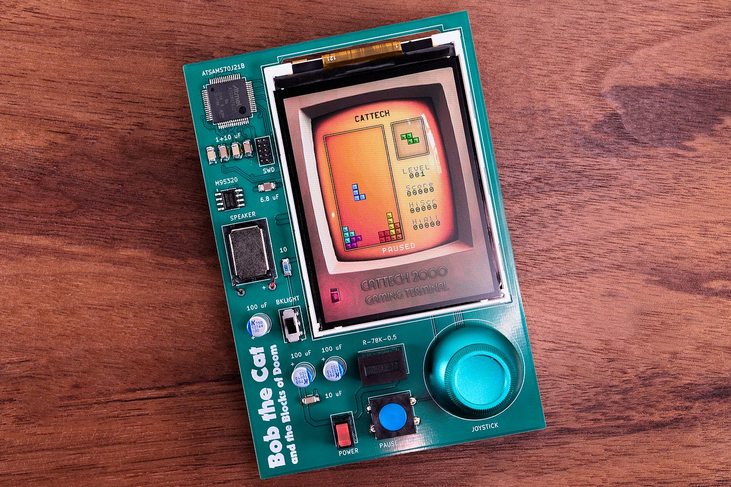
Anyway, with too much time on my hands, I recently decided to take this idea even further, and build a UX that could hold a candle to modern-day smartphone games. I present to you another great homage, Bob the Cat and the Blocks of Doom:
The project involved roughly one week of work and only about 1,000 lines of C code (not counting comments, empty lines, serialized chiptunes, and bitmaps). In this article, I’m going to discuss how I pulled it all off.
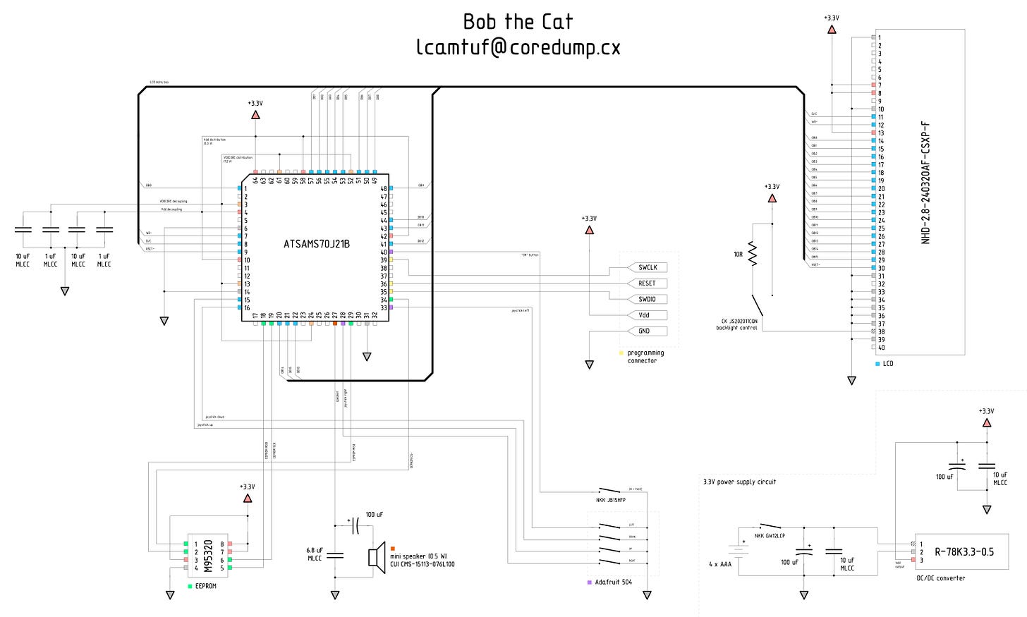
You can download the complete source here and follow along. I also put together a page with schematics and PCB plans for folks who want to build a more polished version at home — but for now, let’s focus on the design process, not the finished board.
Display hardware
The heart of the project is a 240×320 in-plane switching LCD panel from Newhaven Display (NHD-2.8-240320AF-CSXP-F). I chose it because of its very low cost ($29), a suitable form factor, and a fast 16-bit parallel data bus. But above all, the display just looks gorgeous — about as good as OLED panels, and you can’t buy a 3” OLED panel for anywhere near that price.
The panel’s resolution may appear unacceptably low by today’s standards, but the video clearly tells a different story. We’ve come to use resolution as a proxy for image quality, but most of the perceptual improvements achieved in the past two decades have little to do with pixel counts alone. There are three other phenomena at play:
Massive strides in imaging technology, including camera sensors with great dynamic range, little noise, and no bleed.
Vast improvements in bandwidth, memory, and CPU power, permitting higher bitrates, increased color depths, and higher-fidelity compression.
The development of displays with higher contrast, wider gamut, better viewing angles, and faster response times.
I featured this exact panel in a recent article, so I won’t go over the implementation details again, but the protocol is a straightforward variation of the “8080” bus familiar to many MCU enthusiasts — and the code to initialize it and stream bitmap data at up to 200 fps is only about 64 lines long (tft.c).
The brains of the operation
For my earlier game — a clone of Sokoban — I deliberately picked an 8-bit microcontroller. I wanted to push the platform a bit to demonstrate that full-color graphics, smooth animations, and high framerates can be achieved in such a constrained environment without jumping through too many hoops.
For Bob the Cat, this math didn’t quite work out. It wasn’t about computing power or RAM, but about non-volatile program and data storage. Most 8-bit chips max out at 128 kB. To deliver cool-looking graphics, I needed to bundle a fair number of full-color bitmaps, and therein laid the problem: a single full-screen image for the 240×320 panel takes up 150 kB.
Lossy compression algorithms, such as JPEG, can save space — but repeated decompression for every screen refresh would cut into the 8-bit compute budget and add unnecessary complexity. Another option would be to add a separate flash memory chip — but having it stream data at screen refresh rates would be a challenge of its own.
Ultimately, it made more sense to go with a 32-bit MCU. I wasn’t sure about the final memory footprint of the game, so I started developing on Microchip’s ATSAMS70J21B MCU (a chip previously featured here — and now evidently rechristened to PIC32CZ2051CA70064). The main selling point was 2 MB of program memory; the chip’s 300 MHz peak speed was clearly an overkill.
In retrospect, I ended up using only about 625 kB for uncompressed bitmaps and other assets, and that number could be further reduced with minor optimizations. Had I known this ahead of the time, I would’ve saved a couple of bucks and gone with a cheaper ATSAMG55J19A MCU (512 kB of program memory and a 120 MHz clock).
The graphics engine
The panel driver (tft.c) provides primitives for synchronously sending RGB bitmaps to the screen. This is what’s used for many of the animations seen in the video, notably including the high-speed cat slide-in on the splash screen.
The LCD code is supplemented by a higher-level graphics library (display.c). The library divides the screen into an array of 8×8 pixel cells; each of the cells can hold a sprite or a text character. This is a simplified version of the display library developed for Sir Box-a-Lot. In contrast to its predecessor, it lacks pixel-level sprite displacement features that aren’t useful for this particular game.
The key point is that any modifications to the sprite grid are automatically and asynchronously propagated to the LCD. This happens because of a 1 kHz hardware timer (TC0) running in the background and periodically triggering an IRQ. The handler for that IRQ scans the cell grid, picks up “dirty” rows, selectively recomputes small portions of the output bitmap, and then sends the data to the panel.
The source for all this screen refresh logic spans around 150 lines of C code.
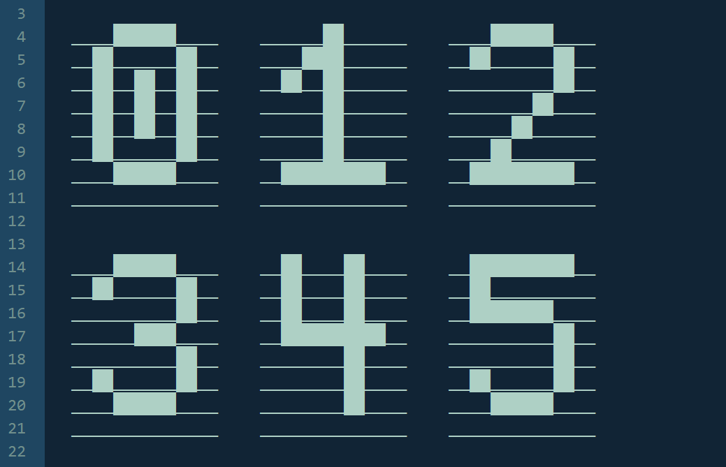
In addition to the library itself, I also hand-crafted a custom reduced-charset 8×8 font to be used for scores, player names, and other simple dynamic text. The font is fairly similar to the 6×6 typeface I developed for an OLED panel last year. It’s inspired by the ZX Spectrum font from the 1980s, albeit it’s more slender and modernized in several other ways:
All the other bitmap assets were fairly straightforward to create, although getting them right still took a couple of days. The computer-themed backgrounds were created from stock imagery, albeit modified substantially in Affinity Photo. Many other elements, including block sprites, were drawn by hand.
Audio playback
Modern MCUs are either equipped with on-board digital-to-analog converters (DACs), or can be easily fitted with an external one. With this in place, it’s possible to produce sine waves and faithfully play back waveform file formats, such as WAV or MP3.
Alas, waveform files tend to be rather massive by microcontroller standards, even if we’re talking about 32-bit chips: an uncompressed thirty-second recording of passable quality takes up about 1 MB. As with bitmaps, I could conceivably use external storage for such assets — but in keeping with the game’s scrappy character, I wanted to get creative with simpler square-wave beeps.
The resulting audio engine — sound.c (50 lines) — piggybacks on the same utility IRQ as the display code. It parses a simple “chip tune” format consisting of a sequence of tuples specifying tone frequency (Hz) and duration (milliseconds). A simple “sad trombone” sound might be:
static const struct chip_note snd_game_over[] = {
  { 200, 300 }, { 0, 200 }, { 190, 300 }, { 0, 200 },
  { 180, 300 }, { 0, 200 }, { 160, 500 }, { 0, 0 }
};
Zero-frequency “notes” encode silence; there is also a special value for looping a tune.
This is conceptually similar to how melodies were encoded in some of the early computer games in the 1980s, so I was hoping to find and reuse some spiffy old track. Sadly, there’s very little that I could find on the internet: whatever might have been published back in the day is probably lost for good. Eventually, a person on Mastodon pointed me toward RTTTL: a similar ringtone format developed by Nokia in the 1990s. There are several collections of RTTTL tunes on the internet, and with the help of my custom playback and conversion tool (utils/convert_rtttl.c), I was able to come up with a soundtrack for the game.
Astute readers might notice that the sound captured in the video doesn’t actually resemble square-wave beeps, which are rather bland and unpleasant to listen to. Instead, the audio has a far more interesting, polyphonic quality with fuzzy harmonics. To understand what’s going on, I should note that the audio engine offloads the actual wave generation to a hardware pulse-width modulation (PWM) circuit onboard the MCU. I experimented with how to improve sound quality on the cheap, and noticed that starting at 50% duty cycle, but then reducing the value as the note plays, produces this spiffy result. An extra lowpass capacitor placed in parallel with the speaker took care of some of the inevitable higher-frequency harmonic hiss that creeped up on the tail end of each note.
It is worth noting that the MCU features four independent PWM channels, so it would be possible to implement zero-overhead polyphony. Each PWM channel outputs to a separate pin, so some external mixing would be required. For two-channel polyphony, it’d be sufficient to place a speaker across two PWM outputs. For full four-channels, external XOR gates would be necessary; a classic 74AHC86 chip should do.
Implementing game logic
The actual game proved to be the easiest part of the project; with all the custom-tailored hardware abstractions in place, it took me a couple of hours to get it to work. To be fair, the abstractions did a lot of the heavy lifting, but some of this would be needed even with a fully-fledged OS in place.
Of course, it was still a bit of a mental workout to get the game mechanics right. Consider, for example, that each piece has different dimensions and a different apparent center of gravity, and there’s no general solution to how to rotate every element on a grid without the movement seeming unnatural and the piece shifting around too much. Handling rotations near walls or other colliding objects is another can of worms — and a source of some controversy among the enthusiasts of this game.
Randomness is an interesting topic too. This particular MCU has a true hardware random number generator, but if you use it to directly select the next piece, the players will get frustrated whenever they get a run of four identical unwanted segments in a row. Instead, the solution is to put all seven possible block shapes in a “bag” (an array), shuffle it, then draw from that bag until it’s empty. This makes the output feel more “random”, because long runs of identical pieces are not possible, and in the short haul, the distribution of pieces is more uniform.
Or, how about input handling? Players want to be able to hold down direction buttons to execute rapid moves — and as it turns out, there’s no repeat rate fast enough for sustained button inputs to feel responsive, yet slow enough to avoid misinterpreting single taps as multiple keypresses. The solution is to have an extended delay (200-250 ms) for the first repeat, followed by shorter intervals (~100 ms) for subsequent repeats. On your PC keyboard, you get that behavior for free. On an MCU, you gotta think it through!

👉 For more MCU- and electronics-related articles, click here.
I write well-researched, original articles about geek culture, electronic circuit design, and more. If you like the content, please subscribe. It’s increasingly difficult to stay in touch with readers via social media; my typical post on X is shown to less than 5% of my followers and gets a ~0.2% clickthrough rate.


I really appreciate these posts. As a software engineer I've been tinkering with a bit of electronics and really want to put something together "from scratch", but there's quite a lot to get in to. Your series is such an inspiration and studying how you've put things together is both fun and educational. I wish there was a "zero-to-handheld console" electrical engineering course to do... but this together with Andre LaMothe's general EE course is the next best thing.
Thank you for the post, always enjoy reading them! Which software did you use to create the circuit layout diagram?