
Cursed circuits #3: true mathematics
Op-amp arithmetics -explained in a more accessible way
In the previous installments of Cursed Circuits, we looked at two switched capacitor circuits: the voltage halver and the capacitor lowpass filter.
In today’s episode, I’d like to talk about the use of operational amplifiers to do something other than amplification: to solve analog math. Analog computing at a scale is wildly impractical because errors tend to accumulate every step along the way; nevertheless, individual techniques find a number of specialized uses, perhaps most prominently in analog-to-digital converters. Let’s have a look at how it’s done.
The following assumes familiarity with core concepts in electronic circuits and with the fundamentals of signal amplification. If you need a refresher, start with the two linked articles first.
Op-amps at a glance
Before we get to less obvious circuits, let’s start with a brief recap: operational amplifiers are to analog electronics what logic gates are to digital logic. They are simple but remarkably versatile building blocks that let you accomplish far more than appears possible at first blush.
Unfortunately, in introductory texts, their operation is often explained in confusing ways. All that an op-amp does is taking two input voltages — Vin- (“inverting input”) and Vin+ (“non-inverting input”) — and then outputting a voltage that’s equal to the difference between the two, amplified by a huge factor (AOL, often 100,000 or more) and then referenced to the midpoint of the supply (Vmid). You can write it the following way:
That’s all the chip does. Because the gain is massive, there is a very narrow linear region near Vin- = Vin+; a difference greater than a couple of microvolts will send the output toward one of the supply rails. The chip doesn’t care about the absolute value of Vin- or Vin+ it can’t “see” any external components you connect to it, and its internal gain can’t be changed.
To show the versatility of the component, we can have a quick look at the following circuit that you might be already familiar with — a non-inverting amplifier:

One input of the op-amp is connected to the external signal source: Vin+ = Vsignal. The other input is hooked up to a two-resistor voltage divider that straddles the ground and the output leg; the divider’s midpoint voltage is:
As discussed earlier, the only way for the op-amp to output voltages other than 0 V or Vsupply is for Vin+ to be very close to Vin-. We can assume that we’re operating near that equilibrium point, combine the equations for the voltages on the two input legs, and write:
Solving this for Vout, we get:
In other words, the output voltage is the input signal amplified by a factor of 1 + Rf/Rg. We have a near-ideal single-ended voltage amplifier with a configurable gain. Again, the circuit is probably familiar to most folks dabbling in analog electronics, but it’s worth pondering that we implemented it by adding a couple of resistors to a chip that does something conceptually quite different.
Note: there’s a bit more to op-amp lore when dealing with high-frequency signals; a more rigorous analysis of their frequency characteristics can be found in this article.
Addition
Now that we have the basics covered, we can show that op-amps can do more than just amplify signals. The first contender is the following summing layout that differs from what’s usually covered in textbooks, but that’s well-suited for single-supply use:
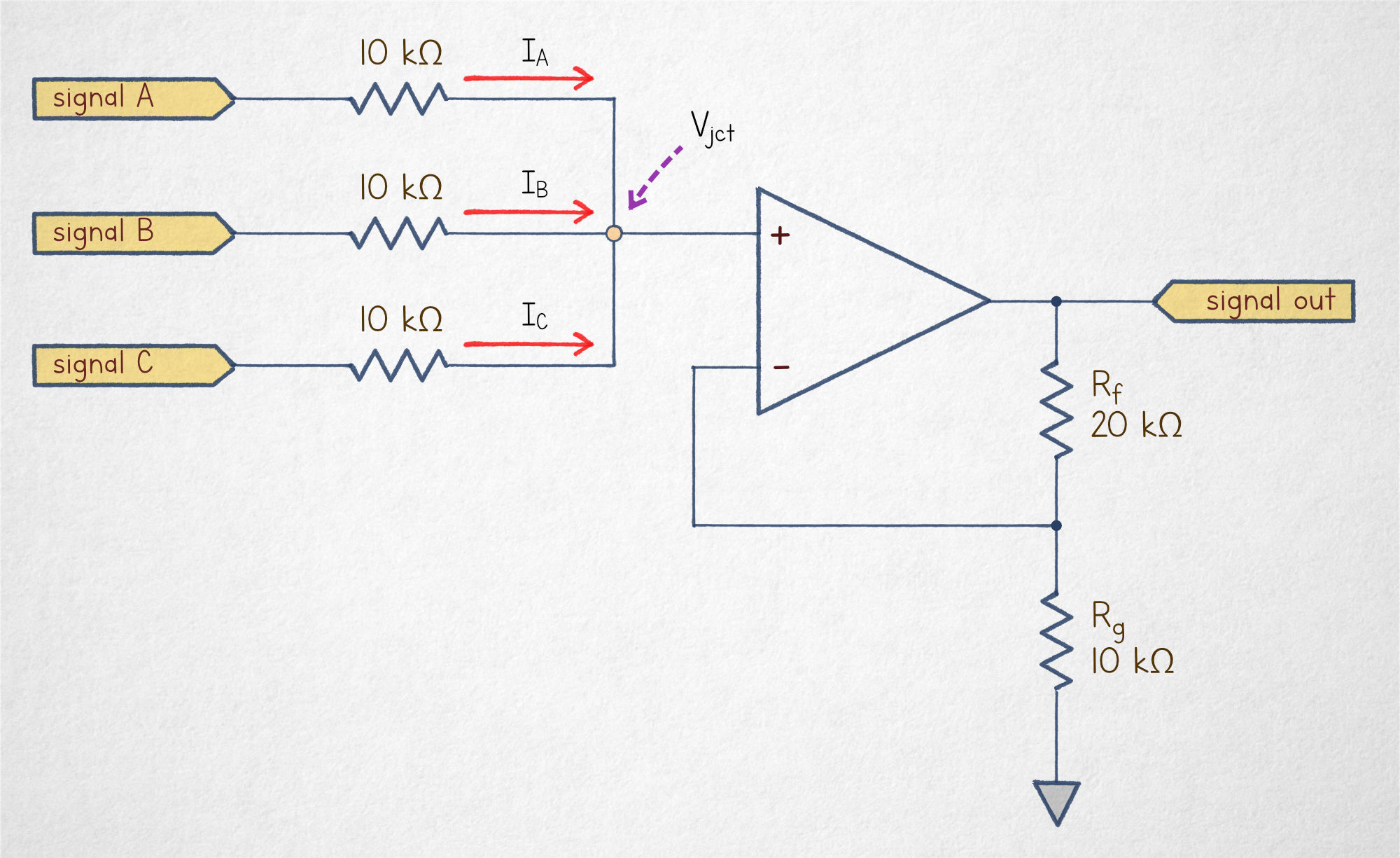
Assuming well-behaved signal sources that can supply and sink currents, it should be pretty intuitive that the voltage on the Vin+ leg is just an average of three input signals:
For readers who are unpersuaded, we can show this from Kirchoff’s current law (KCL); the law essentially just says “what comes in must come out” — i.e., the currents flowing into and out of the three-resistor junction must balance out. If we use Vjct to denote the voltage at the junction, then from Ohm’s law, we can write the following current equations for each resistor branch:
Further, from KCL, we can assert that the currents must balance out: I1 + I2 + I3 = 0 A. Combining all these equations and multiplying both sides by R, we get:
Solving for Vjct, we get (VA + VB + VC) / 3. We have a confirmation that the input-side resistor section averages the input voltages.
To be fair, the averaging portion of the circuit has a minor weakness: it depends some inputs sinking current while others source it. Some signal sources might not have that ability. That said, compared to the alternative design, it has the benefit of being more useful in single-supply circuits, so let’s stick with that.
Moving on to the op-amp section: this is just another sighting of the non-inverting amplifier. The gain of the amplifier circuit is set by the Rf and Rg resistors, and in this instance, works out to A = 1 + Rf/Rg = 3. In other words, the signal on the output leg is:
That looks like a sum! But it also feels like we cheated in some way: it just so happens that we could implement averaging using passive components, and then tack on an amplifier for some gain. Surely, resistor magic can’t get us much further than that?
Subtraction
It can! The next stop is subtraction, which can be achieved with the following circuit topology:
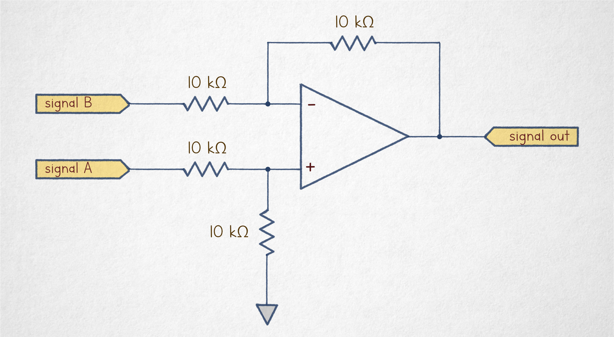
We can start the analysis with the non-inverting input of the amplifier. The signal on this leg is generated by a voltage divider consisting of two identical resistances connected in series between VA and the ground. In other words, the voltage here is Vin+ = ½ · VA.
The inverting input is a voltage divider too, except it produces a voltage that’s halfway between VB and Vout: Vin- = ½ · (VB + Vout).
As with any op-amp topology, linear operation can happen only when Vin- ≈ Vin+. In other words, we can assert that for the circuit to function, the following must be true:
We can cancel out the repeated ½ term on both sides, and then reorder the equation to:
Neat: that’s precisely what we’ve been trying to do.
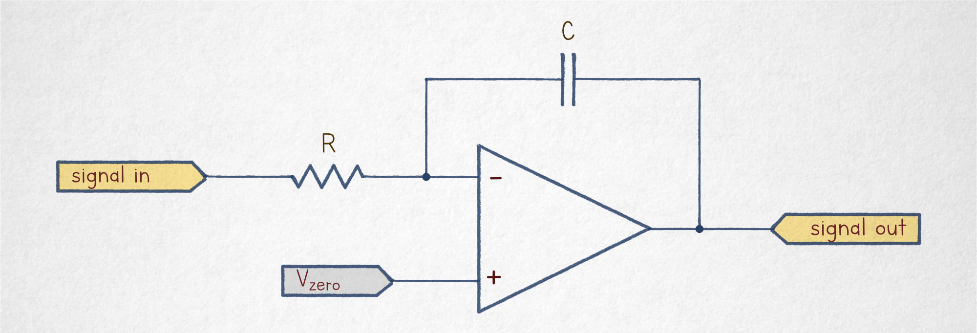
To be fair, not all is roses: in a single-supply circuit, an op-amp can’t output negative voltages, so the topology we’ve just analyzed works only if VA > VB; otherwise, Vout just hits the lower rail and stays there until the input voltages change.
To accommodate use cases where VA < VB, we’d need to use a higher output voltage as the “zero” point (Vzero). For example, if Vzero = 2.5 V, then a computed difference of -1 V could be represented by Vout = Vzero - 1 V = 1.5 V; in the same vein, a difference of +2 V could correspond to Vout = 4.5 V.
To do this, we just need to disconnect the bottom voltage divider from the ground and replace 0 V with a fixed “zero” voltage of our choice. This changes the equation for the positive leg to Vin+ = ½ · (VA + Vzero). The overall equilibrium condition becomes:
After tidying up and solving for the output signal, we get:
A common choice of a reference point would be the midpoint of the supply (Vmid = ½ · Vsupply).
Multiplication and division
The concept of analog computation can be also extended to multiplication and division. The most common and mildly mind-bending approach hinges on the fact that any positive number can be rewritten as a constant base n raised to some power; for example, 8 can be written as 23, while 42 is approximately 25.3924.
From the basic properties of exponentiation, it’s easy to show that na · nb is the same as na+b; it follows that if we have two numbers represented as exponents of a common base, we can reduce the problem of multiplication to the addition of these exponents.
We already know how to build a summing circuit, so all we’re missing is a way to convert a number to an exponent. We don’t really care what base we’re using, as long as the base remains constant over time.
This brings us to the following design:
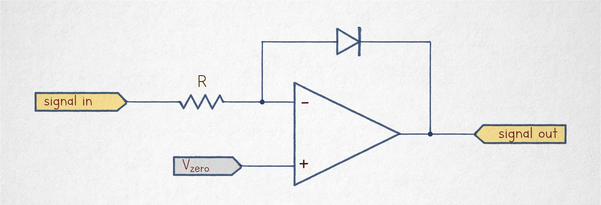
As before, the linear equilibrium condition requires Vin- ≈ Vin+. Let’s assume that the initial input voltage is about equal to Vzero; in this case, the output settles in the same vicinity.
Next, let’s analyze what would happen if the input voltage increased by vs = 100 mV. In such a scenario, for the op-amp to stay at an equilibrium of Vin- ≈ Vin+, we would need a sufficient current to flow through the resistor to create a 100 mV voltage drop:
The op-amp has a very high input impedance, so the current must flow through the diode; if it doesn’t, that’d move the circuit toward a condition of Vin- ≫ Vin+, which would cause Vout to move toward the negative supply rail. That would forward-bias the diode and thus motivate it to conduct better. In other words, the circuit has an automatic mechanism that coerces the diode to admit the current matching IR, and the amount of convincing is reflected in how much the output voltage has been reduced from the midpoint. We can denote this relative shift as vo.
From an earlier feature about diodes, you might recall that although the relationship between the applied diode voltage and the resulting current is complicated, there is an initial region where the component’s V-I curve is exponential. In the following plot for a 1N4148 diode, this property holds up for currents up to about 1 mA:
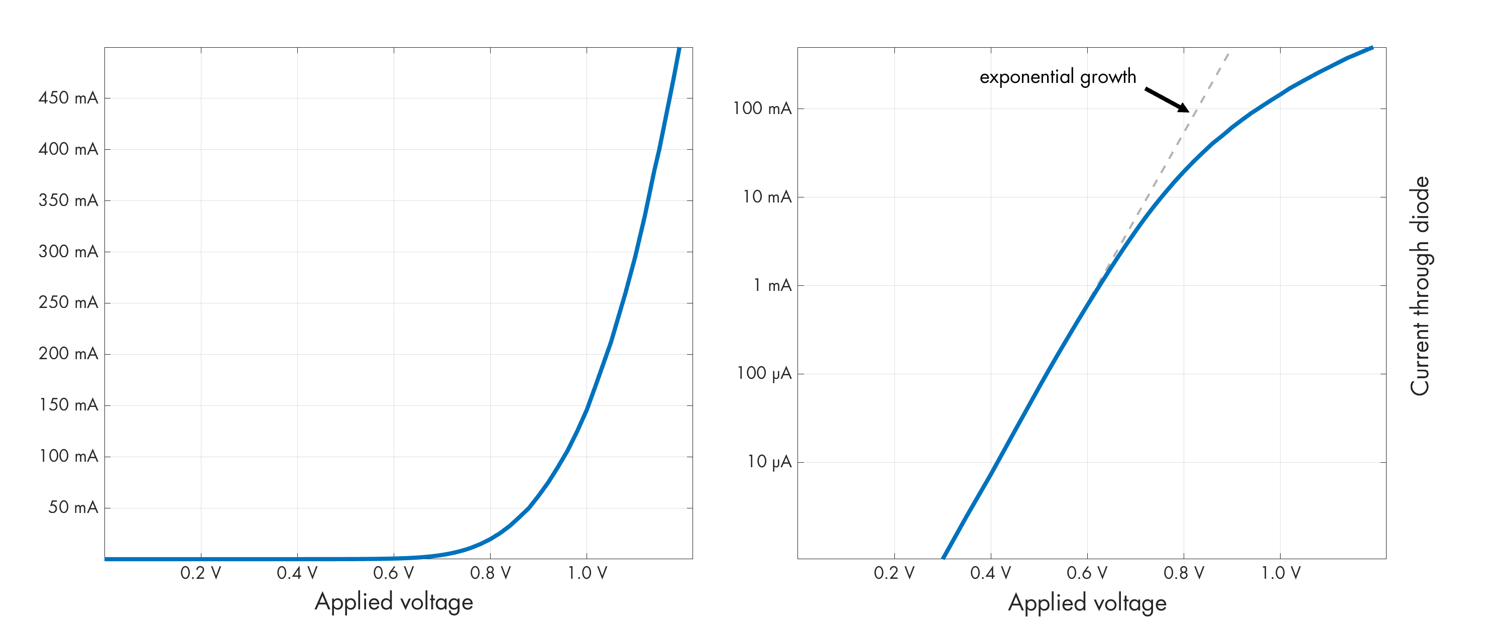
In other words, if the input resistor is large enough (10 kΩ or so), we can say that vo will be dictated by the magnitude of an exponent of some constant base n that yields the correct diode current: ID = nvₒ.
We also know that the current that must flow through the diode is proportional to the shift in the input signal (vs) divided by R. This means that we’ve accomplished the number-to-exponent conversion between vs and vo. Or, in the mathematical parlance, we’ve calculated a logarithm.
To implement multiplication, we need two logarithmic converters on the input side, a summing amplifier to add the exponents, and then an exponential converter that goes from the summed exponent back to a normal value. That last part can be accomplished by switching the location of the diode and the resistor in the log converter circuit we already have.
Integration
Integration is just a fancy word for summing values over time; if you want to sound posh, you can say that a bucket in your backyard “integrates” rainfall over the duration of a storm.
Although integration is important in calculus, analog integrators have down-to-earth uses too. For example, the circuits can convert square waves into triangular shapes that are useful in electronic musical instruments. The circuit’s ability to produce very linear up and down slopes also comes in handy in slope-based and delta-sigma ADCs.
The simplest, textbook integrator is shown below:
Once again, we can note that the linear operation condition is Vin- ≈ Vin+. Further, let’s assume that the input signal is equal to Vzero and the capacitor is discharged, so both op-amp inputs and the output are at about the midpoint.
Next, similarly to the analysis we’ve done for the log amplifier, let’s assume that the input signal shifts up by vs = 100 mV. For the op-amp to stay at an equilibrium, we would need a sufficient current to flow through the resistor to create a 100 mV voltage drop: IR = vs/R.
The only possible path for this current is the capacitor; a capacitor doesn’t admit steady currents, but it will allow the movement of charges during the charging process, which will kick off when the op-amp’s output voltage begins to drop; this drop causes a voltage differential appears across the capacitor’s terminals.
From the fundamental capacitor equation, charging the capacitor with a constant current IR for a time t will produce the following voltage across its terminals:
To keep Vin- steady, the voltage to which the capacitor gets charged must be accounted for by a directionally opposite shift of the output voltage (vo). The shift will persist after Vsignal returns to the midpoint, because with no charging or discharging current, the capacitor just retains charge. The shift can be undone if vs swings the other way around.
From the earlier formula for the capacitor voltage, it should be clear that the circuit keeps a sum of (midpoint-relative) input voltages summed over time.
The textbook integrator we’ve been working with has an inverted output: Vout moves down whenever Vsignal moves up; this makes it somewhat clunky to use in single-supply applications. The problem can be addressed in a couple of intuitive ways, but a particularly efficient — if positively cursed — solution is shown below:
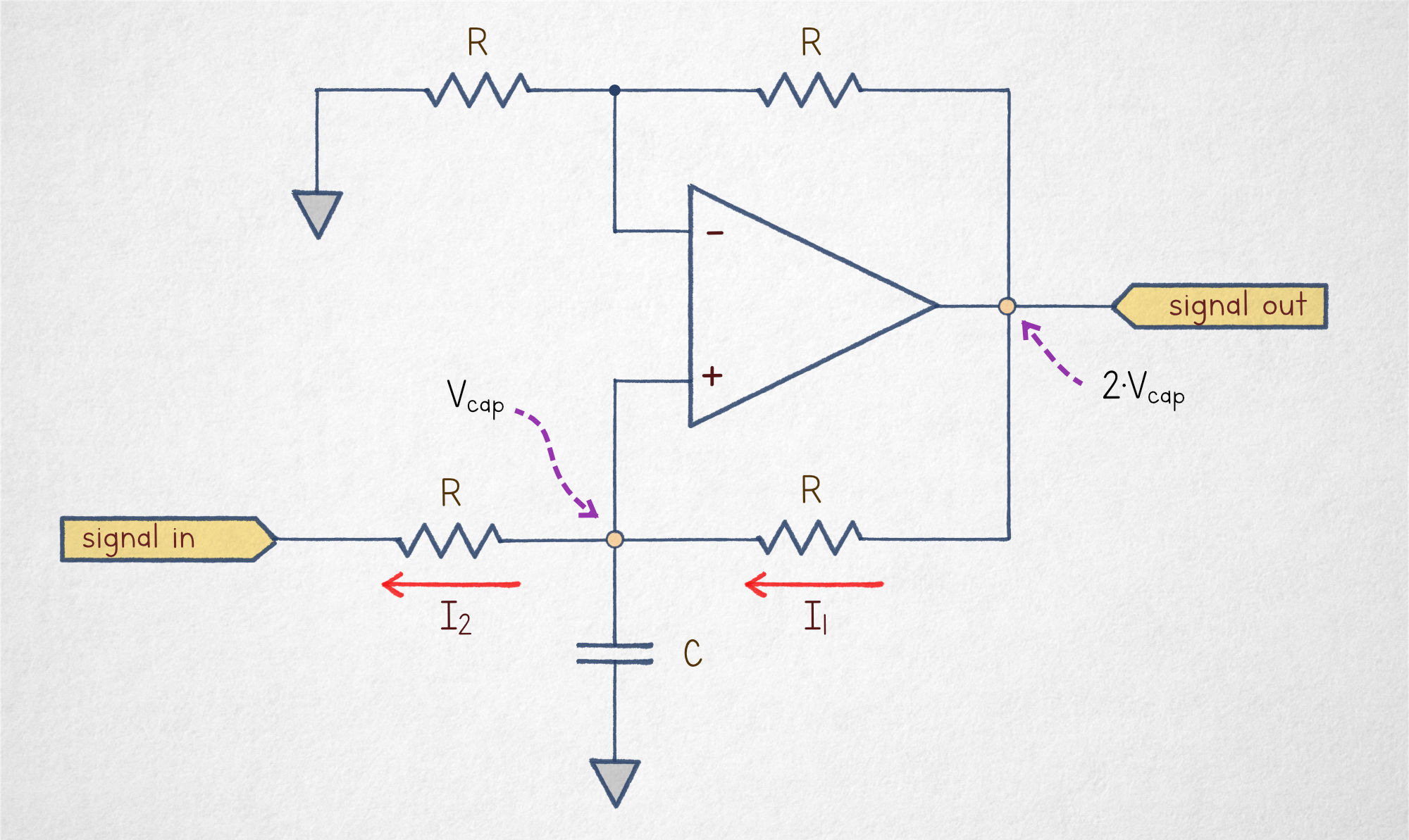
As in all other cases, the prerequisite for linear operation is Vin- ≈ Vin+.
We can start the analysis with the two-resistor divider on the top: it simply ensures that Vin- is equal to ½ · Vout. As the bottom portion of the circuit, the instantaneous voltage on the non-inverting input is decided by the capacitor’s charge state (Vcap). The bottom resistors will influence the charge of the capacitor over time, but if we’re living in the moment, we can combine the equations and write the following equilibrium rule:
Equivalently, we can say that Vout ≈ 2 · Vcap.
We have established that Vout is equal to twice the value of Vcap, but if so, the resistor on the bottom right is subjected to a voltage differential between these two points (always equal to Vcap). From Ohm’s law, the resistor will admit the following current:
If the input voltage is zero, the neighboring resistor to the left is subjected to the same voltage differential, so the current flowing into the junction (I1) is the same as the current flowing out (I2). With the currents in balance, the capacitor holds its previous charge and the output voltage doesn’t change.
That said, if the input voltage (Vsignal) is non-zero, the voltage differential across the terminals of the resistor on the left is different, and the formula for I2 becomes:
In this case, there is a non-zero balance of the currents flowing in and out via the resistors:
This current is flowing in via the resistor on the right but not flowing out via the resistor on the left, so it necessarily charges the capacitor. Note that the capacitor charging current is independent of Vcap; it remains constant as long as the input voltage is constant too.
As before, from the fundamental capacitor equation (V = I·t/C), we can tell that a constant charging current will cause the voltage on the output leg to ramp up in a straight line. Of course, this will come to an end once we hit the output voltage limit of the amplifier. To reset the circuit, we’d need to short the terminals of the capacitor.
👉 For further articles about electronics, click here. In particular, you might enjoy:


I write well-researched, original articles about geek culture, electronic circuit design, algorithms, and more. If you like the content, please subscribe.
Just some meta commentary for what follows here: I make mistakes every now and then and I always welcome corrections, questions, and friendly banter from subscribers. That said, in this instance, after a spirited exchange in the comments section below, I do stand by the article :-)
The TL;DR is that a subscriber expressed concern that the non-inverting summing amplifier presented in the circuit may not work correctly. I think that in the general case, it should. If you're looking for independent references to the circuit, see the relevant section in https://www.ti.com/lit/an/snla140d/snla140d.pdf
Now, there is an important distinction between the non-inverting architecture presented in the article and the "textbook" inverting summing amplifier that you will, for example, find in "The Art of Electronics". The distinction is that in the non-inverting design, the current is necessarily flowing in through some of the input legs and flowing out through others. This can cause problems if one of the sources can only source currents, but not sink any (e.g., if it includes a series diode). The inverting variant, on the other hand, keeps the junction point near 0 V. Because of this, for positive input voltages, all the currents are flowing in the same direction and the drive constraint is eased.
In other words: I agree that in some situations, the inverting architecture may be preferred. That said, I believe the circuit presented in the article is reasonable. I did not use the inverting layout because it works as advertised only in a dual-supply circuit. The inverting summing amplifier *can* be converted to to single-supply operation, but that necessarily involves putting the summing point at a higher voltage and breaks the symmetry with the difference amplifier.
Your adder might not work the way you expect. Those three input resistors normally drive the virtual ground at the - input.